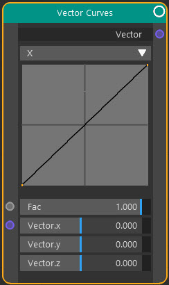
Vector: Vector Curves
Node Interface
Overview
| Function | Alters vectors by mapping the input value of each component to a different output value. |
| Nearest C4D equivalent | None |
This node is very similar to the RGB Curves node but manipulates a vector input instead of a colour.
You cannot edit the curves directly in the node. To edit the curve, select the node and then in the Node Settings tab of the right-hand pane of the node editor, or in the attribute manager, select the component to edit and you can then edit the curve. If you need a larger window (perhaps because you need to make some precise edits) double-click the curve you want to edit in the node, and a separate window will appear, which you can enlarge as much as required.
Settings
Note: a * symbol next to the name indicates the parameter also has an input port. A # symbol indicates that the parameter can only be changed with an input node, not in the node itself.
Component drop-down menu
This lets you choose the vector component to edit. Select X, Y, or Z to edit the selected component.
Curve
This is the curve for the selected component. Note that you cannot edit the curve in the node. To edit it, go to the Node Settings or attribute manager and edit the curve there.
Fac *
The overall strength of the effect. A value of 0.0 means no effect at all; a value of 1.0 gives the maximum effect.
Vector *
You can change the three components of the vector directly in this parameter, but you can input a vector from any other node which has a Vector output. For example, you could link the output from a Bump node and alter the resulting vector using the curves.
Output
Vector
The altered vector.