Texture: Wave
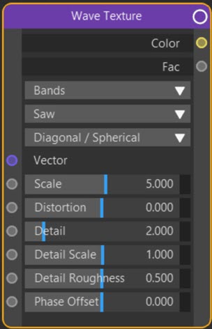
Node Interface
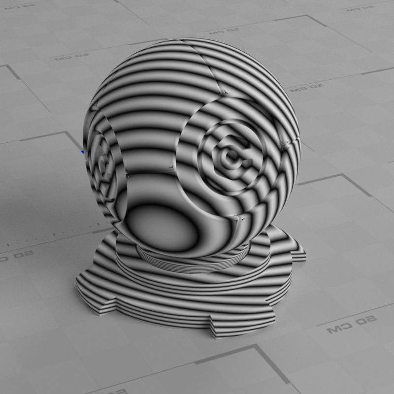
Example Output
Overview
| Function | Produces a wave-like pattern |
| Nearest C4D equivalent | Water shader |
This node generates a wave-like pattern which is not very useful in the default state but is much more so when distorted and detail is added.
Settings
Note: a * symbol next to the name indicates the parameter also has an input port. A # symbol indicates that the parameter can only be changed with an input node, not in the node itself.
Type drop-down menu
The two possible types are:
Bands
Generates lines across the object.
Rings
Produces rings across the object.
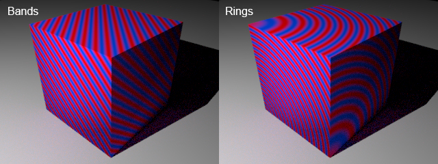
You won't see much, if any, difference in these types when applied to a spherical object, but applied to a cube the difference is clear:
Profile drop-down menu
By default the nodes uses a sawtooth wave to produce the bands or rings, but can also use a sine wave or triangles instead.
Direction drop-down menu
 The bands or rings will be perpendicular to the axis (X, Y or Z) selected in this menu. There is also another option - 'Diagona/Spherical'. 'Diagonal' only applies if 'Type' is set to 'Bands'; a diagonal axis is used. 'Spherical' only applies if 'Type' is set to 'Rings' in which case the rings form concentric circles from a single point on the surface. You can see the effect in the above image.
Vector #
The coordinate system to use for projecting the texture. You can link a Texture Coordinate node to this port, for example.
Scale *
This changes the size of the texture, but as is common in Cycles 4D, increasing the scale increases the 'amount' of texture used, so it appears smaller on the object.
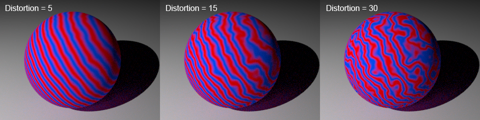
Distortion *
Increasing this value will start to distort the parallel or concentric lines:
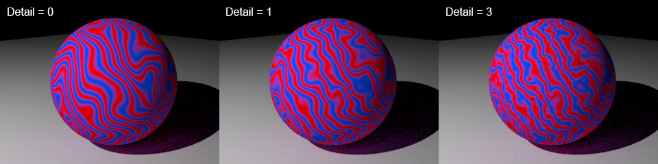
Detail *
This setting increases noise detail on the bands:
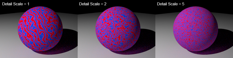
Detail Scale *
This setting scales the noise added by the detail setting. If set to zero, you will see no distortion or detail. Remember that in Cycles 4D increasing the scale actually increases the 'amount' of texture used to cover the area, but in turn the texture will become smaller:
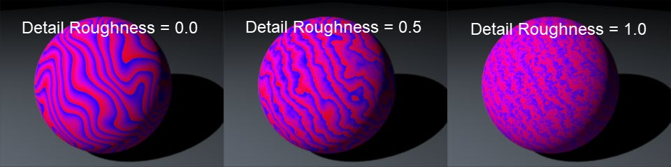
Detail Roughness
The amount of 'roughness' in the detail. These examples should make it clearer:
Phase Offset
This parameter offsets the bands/rings along the direction given by 'Direction'. You can keyframe this value to give a rippling effect across the surface, for example.
Output
Color
The colour output. This is monochrome by default. The above colour images were made by simply linking the Fac output value to the Fac input port of a Color Ramp node.
Fac
The colour brightness.