Using the Node Editor
The node editor is a vital part of Cyles4D. Almost everything you do regarding material creation is done here, and many features such ambient occlusion are added this way. Using the node editor effectively is therefore essential to the use of Cycles 4D.
If you have used Xpresso the node editor is similar to that but, as you will see, is more advanced and far more fully-featured. The basic principles are the same though: add nodes, change their settings, and link them together.
- Opening the Node Editor
- Keyboard shortcuts
- Options menu
- Breadcrumb bar
- Editing the material and nodes
- Aligning nodes
- Other node editor operations
- Frames
- Pivots
- Editor mini-map
For more information, also see these separate manual pages:
and the node reference pages:
Opening the Node Editor
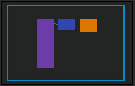
Create a Cycles 4D object material, then double-click it and the node editor will open. It will contain a default node tree for the material that was created, so for an Object Material it would look like this:
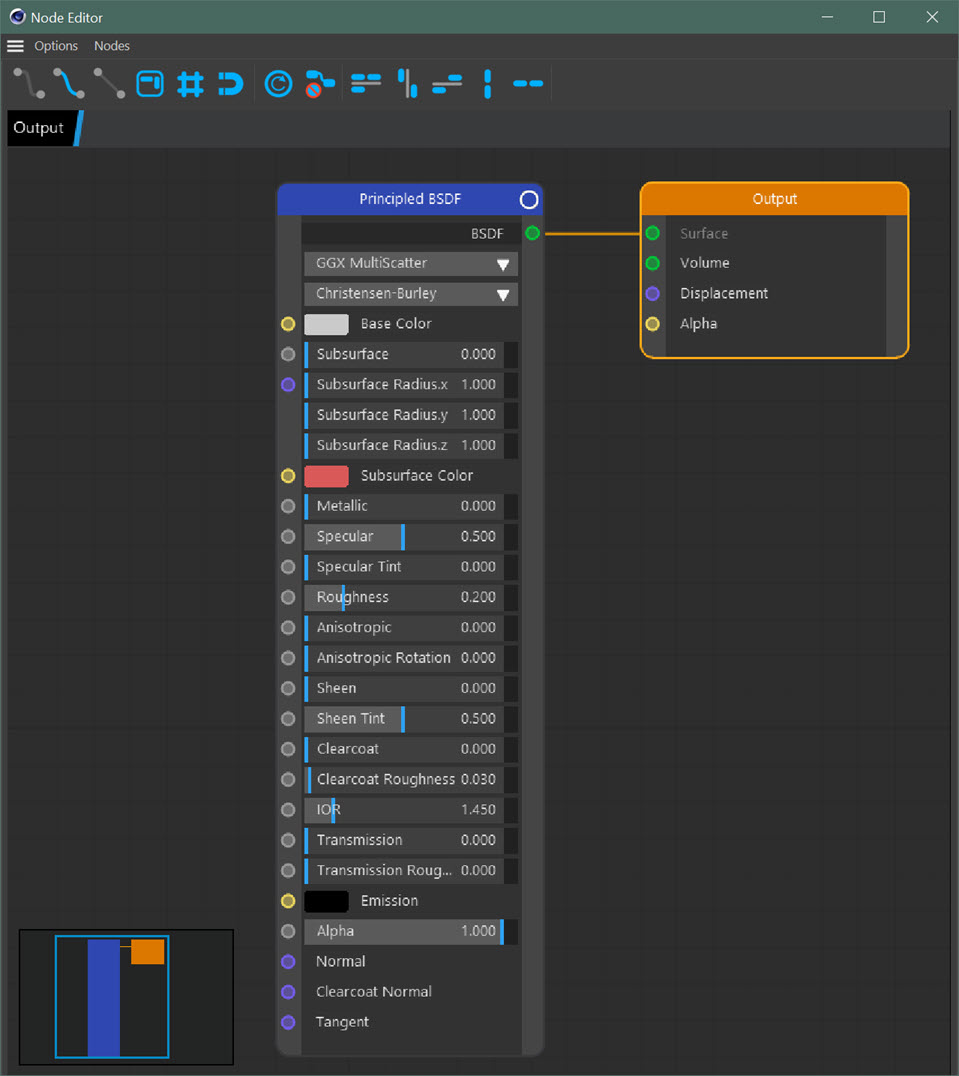
As you can see, it is a blank window with two nodes in it, but you can change that from the Options menu.
Note also the mini-map in the bottom-left corner and the row of buttons along the top.
You can also open the Node Editor from the Cycles 4D menu. If a Cycles 4D material is already selected in the Cinema 4D materials manager, the node tree will be shown in the editor. If no material is selected the node editor will be empty until you select a material.
Icons
The icon strip at the top of the window contains the following icons:
![]()
The first three icons allow you to switch between angled wires when connecting nodes (this is the first icon, with the tooltip 'Small Tangents'), curved lines as in Cinema 4D's Xpresso editor (the second icon, tooltip 'Large Tangent') and straight lines (third icon, tooltip 'Linear'). The other icons are as follows:
| Angled wires between nodes | |
| Curved wires between nodes | |
| Straight wires between nodes | |
| Turn the minimap on or off | |
| Turn the node editor background grid on or off | |
| Turn snapping to the grid on or off | |
| Refresh the node tree inside a group | |
| Delete all unconnected nodes | |
| Sort all nodes | |
| Sort selected nodes horizontally | |
| Sort selected nodes vertically | |
| Align selected nodes horizontally | |
| Align selected nodes vertically |
Note that all these commmands are available in the 'Nodes' menu of the node editor:
See the 'Aligning nodes' section below for details of node sorting and aligning.
Keyboard shortcuts
1Some additional shortcuts have been added in this release of Cycles 4D.
There are a number of keyboard shortcuts you can use in the node editor. They are listed in this table:
| Shortcut | Alternate | Action |
|---|---|---|
| 1 + Left Drag | Middle Mouse Button | Pan the node editor |
| 2 + Left Drag | Mouse Scroll Wheel | Zoom the node editor |
| R | Reset the node editor zoom | |
| H | Frame all nodes (i.e. zoom and pan the editor to show all nodes in the node tree) | |
| S | Frame selected nodes | |
| Space | If a node group is selected, open the group for editing | |
| U | If in an open group, close the group and return to the node editor | |
| Ctrl + A | Select all nodes | |
| Ctrl + D | Deselect all nodes | |
| Shift + Left Click a node | Add the node to any selected nodes | |
| Shift + Left Drag | Draws a rectangle to select multiple nodes and add them to any selected nodes | |
| Ctrl + Left Drag | Draws a rectangle to deselect multiple nodes | |
| Delete | Backspace | Delete selected nodes |
| Alt + G | If one or more nodes is selected, create a new node group and add the nodes to the group | |
| Ctrl + G | If a node group is selected, disband the group and return the nodes to the node editor | |
| Alt + Left Drag over a link | Cut the link between ports | |
| Ctrl + Alt + Left Drag over a link | Inserts a pivot into the link | |
| C | Connect two or more selected nodes | |
| Alt + F | If a node is selected, this will automatically add the node to a new frame | |
| Ctrl + F | If a frame is selected (but not any nodes inside it) the frame will be disbanded | |
| Ctrl + M | If two Shader nodes (e.g. Diffuse BSDF and Principled BSDF) are selected, this will add a Mix shader node and link the output of the two shader nodes to the Mix node | |
| Enter/Return when a node is selected | Allows the node to be renamed | |
| Shift + Double-Click a node title | Allows changing the colour of the node title bar | |
| Tab | Shows the node commander window (see below) |
Options menu
The node editor window has a small menu labelled 'Options' containing these entries:
Show Attributes
Clicking this option will open an attributes pane in the node editor on the right-hand side. This will display the settings for the selected node:
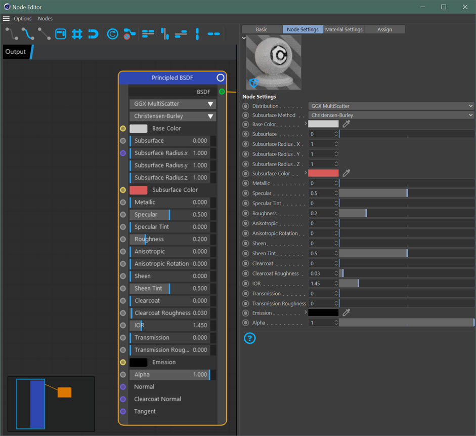
You can remove this to free up space in the editor by clicking 'Show Attributes' again. If you close the attributes pane you can still edit the node settings in the node itself or in Cinema 4D's attributes manager.
Show Node List
If you click this option, a list of all available nodes for this type of material opens in the node editor in a new pane on the left-hand side:
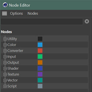
The colour swatches against each node type are the same as are used in the title bar of a node belonging to this type.
You can add a new node to the editor window either by double-clicking the node in the list or by clicking and dragging the node into the editor window.
You can remove this to free up space in the editor by clicking 'Show Node List' again. If you close the node list pane you can still add nodes by right-clicking in the editor window and selecting a node from the context menu which appears.
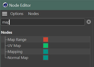
Finally, you can type part of any node name in the text entry field above the list. The node list will then show only those nodes which match what you typed. For example, if you type 'map' you see this:
Node Commander
If you prefer to keep the node list in the sidebar closed to maximise editor space, you can still bring up the list temporarily by pressing the Tab key. If you do that, this small window appears:
You can use this in exactly the same way as the main node list. To remove it, simply click anywhere in the node editor outside this window.
Show Icon Bar
Unchecking this option will hide the icon bar in the node editor.
Show Breadcrumb Bar
 What is the breadcrumb bar? Suppose you have an apparently simple node tree like this:
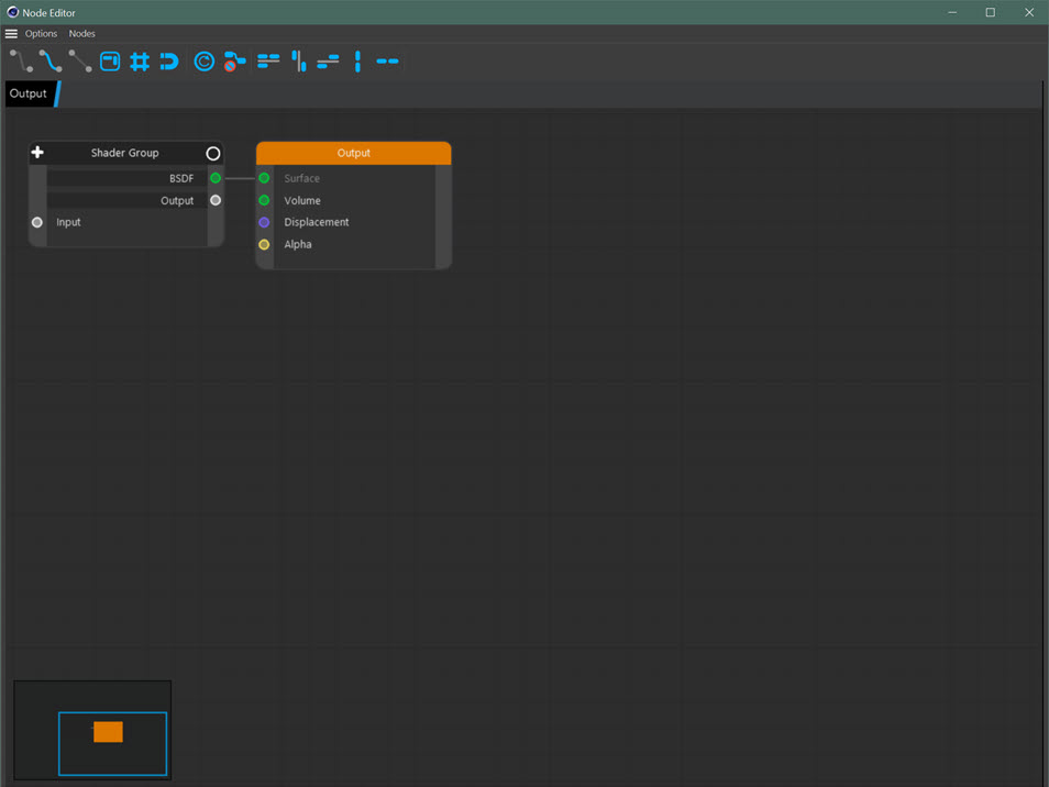
You can see that there is a node group labelled 'Shader Group' in the tree. If you open the group, it looks like this:
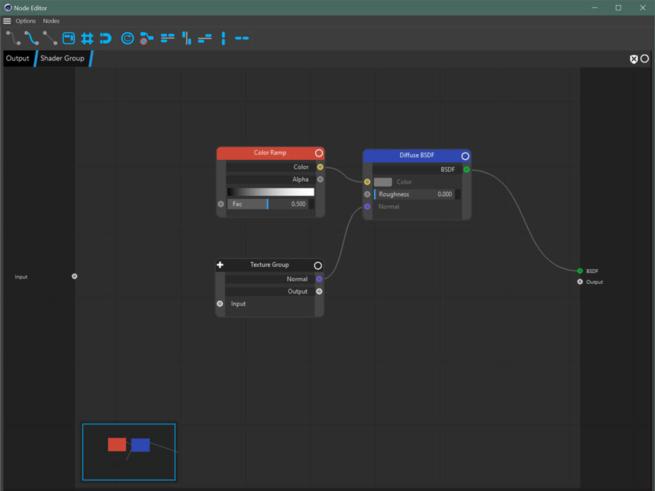
Note that the breadcrumb bar now shows that you are in the group 'Shader Group'. If you click 'Output' in the breadcrumb bar, the group is automatically closed and you return to the original node tree. In the group there is a second group labelled 'Texture Group'. Open that and you see this:
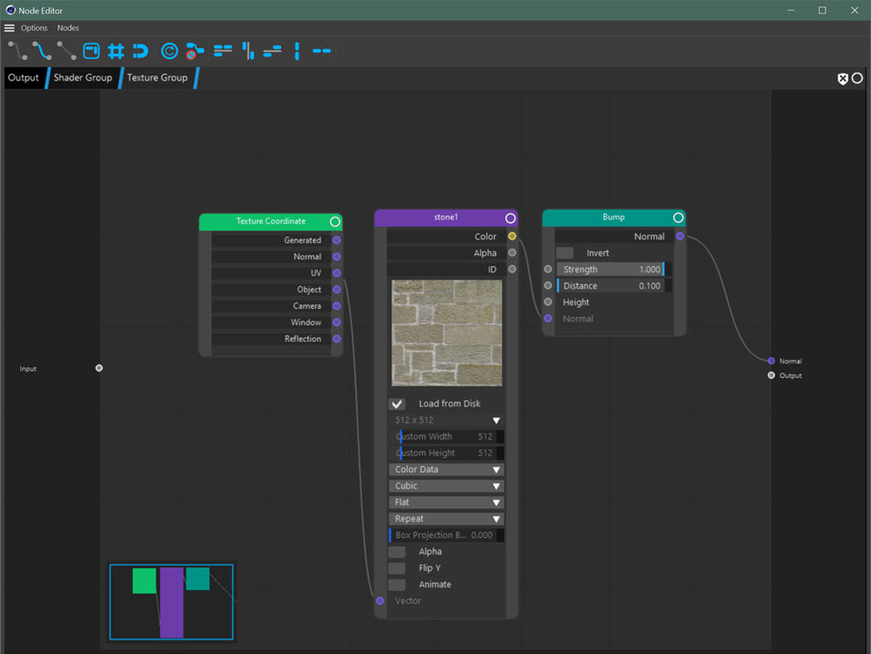
Now the breadcrumb bar tells you that you are in the 'Texture Group' inside the 'Shader Group' inside the main node tree. This can be very helpful since it lets you know exactly where you are in the tree, and you can back out of the nested group to the main tree with one click.
If you don't want to see the bar, uncheck this option in the menu.
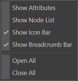
Open All/ Close All
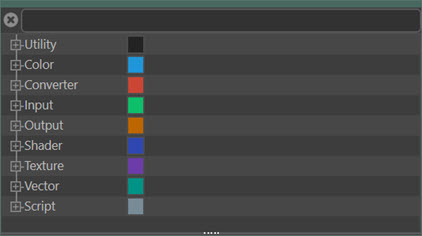
These two menu options only apply to the node list. If you click 'Close All' the submenus are all closed leaving just the group names - Color, Converter, and so on. Clicking 'Open All' opens all the submenus up again.
Finding a node in the list
If you want to find a particular type of node you can type its name or part of it in the edit field at the top of the node list. When you hit Enter, the list is shortened to show only those nodes matching what you typed. So for example, typing 'map' into the field will result in the list showing only those nodes which contain those letters:
Now only the nodes with 'map' somewhere in their name are seen. Simply clear the text field to show all the nodes again.
Editing the material and nodes
Material settings
Changing the overall settings of the material is described on the Cycles 4D Materials page.
Node settings
You can edit the node settings in three places: the node itself, the node editor, or Cinema 4D's attribute manager. To edit the node in the node editor, go to the 'Options' menu and select 'Show Attributes' as described above in the 'Options Menu' section. To select a node, click on it and the material and node settings will appear in the right-hand pane.
As an alternative, you can click a Cycles 4D material to select it in Cinema 4D's material manager, and it will appear in the Attributes Manager as with any Cinema 4D material:
You can then select the Node Settings tab to show the node settings for the node selected in the node editor:
Full details of editing the nodes are given in the 'Editing Node Settings' page.
Aligning nodes
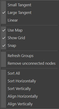
There are two ways to align nodes automatically in the node editor: the context menu and the align icons at the top of the node editor window.
If you right-click in the node editor window to display the context menu there are a number of entries, most of which are relevant to editing specific nodes. These are discussed on other pages. There is one important sub-menu however: the node alignment menu.
If you select two more nodes in the editor, the menu looks like this:
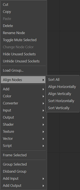
Note that if no nodes are selected, the only option is 'Sort All'.
The equivalent icons are:
![]()
From left to right, these are:
- Sort All
- Sort Horizontally
- Sort Vertically
- Align Horizontally
- Align Vertically
You can hover over any icon with the mouse to show a tooltip indicating which button does what.
Sort All
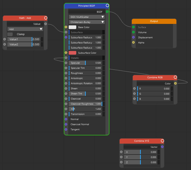
This option will try to move the nodes to align them vertically and horizontally. So a node tree that looks like this:
After 'Sort All' becomes this:
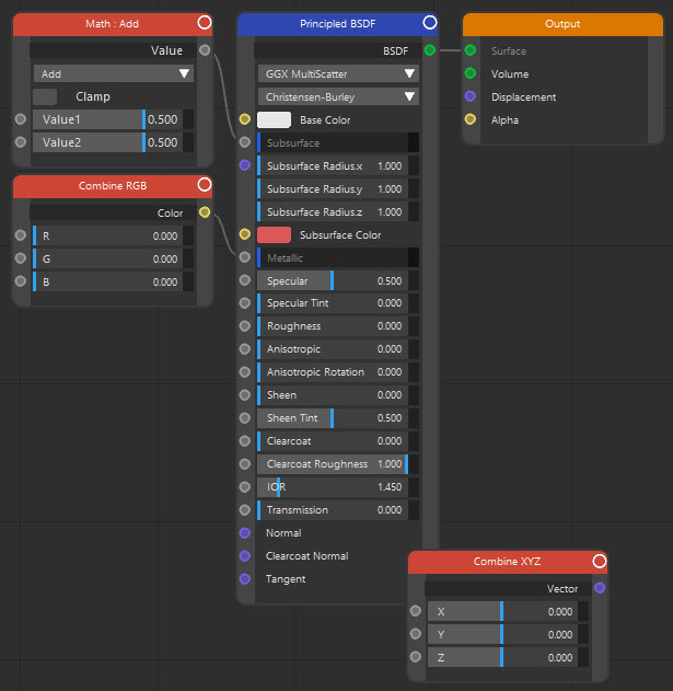
Very importantly, note that this only works on nodes connected to one another. Unconnected nodes are not affected.
Sort Vertically, Sort Horizontally
These options distribute nodes evenly over space in the editor window. 'Sort Vertically' does not move the nodes horizontally but redistributes them so that they are equally spaced vertically. 'Sort Horizontally' does the exact opposite.
Align Vertically, Align Horizontally
These options align the nodes by the tops of the nodes (vertical) or the side edges (horizontal).
Moving around in the editor
You can select nodes in the editor and move them around by dragging with the mouse. You can also select more than one node and drag them all round at the same time.
To move around in the editor you can:
- hold the '1' key and hold the left mouse button then drag the mouse to pan around the editor
- or left-click and drag over the minimap to move the area shown in the editor
- zoom in or out with the mouse wheel or hold the '2' key and hold the left mouse button then drag the mouse to zoom
Material settings
These are settings for the material as a whole, not for individual nodes.
See the Cycles 4D Materials page for details.
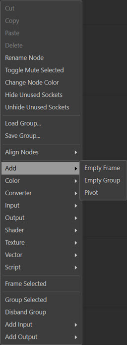
Adding nodes
You can add a node using the node list pane (see above) but you can also use the context menu in the node editor. To add a node, right-click anywhere in the nodes window (the black area) and the context menu appears:
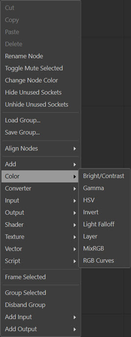
Select the required node from this menu.
The 'Add' submenu is a special case. From this you can add a new frame, group or pivot:
Adding and automatically connecting nodes
If you right-click on an output port of an existing node, a context menu appears with the list of nodes you can add. Selecting any of these nodes will add the new node and automatically create a link between the outport port and an input port of the new node.
Creating nodes from scene objects
You can drag some scene objects into the node editor from the object manager and an appropriate node will be created. For example, dragging a polygon object (not a primitive object) or a light into the node editor will create an Object Info node. The current list of objects and the nodes which are created on dragging the object into the editor is as follows:
| Object | Node created |
|---|---|
| Hair object | Hair Info |
| Light | Object Info |
| Polygon Object | Object Info |
| Selection Tag | Atttribute Node (a Cycles 4D atttribute tag is also created on the object) |
| Texture Tag | Atttribute Node (a Cycles 4D atttribute tag is also created on the object) |
| X-Particles Emitter | Particle Info |
Deleting nodes
To delete a node, select it and hit the Delete key. Or you can select it, then bring up the context menu and select Cut or Delete (Cut first copies the node to the clipboard, then deletes it).
Note that the Backspace key can also be used to delete nodes.
 Sometimes the node may not be deleted when you hit the Delete (or Backspace) key. This is due to a quirk in Cinema 4D's handling of key presses in this environment. If that happens, click the node again and then try the Delete key; alternatively, use the context menu to delete the node.
The context menu also lets you copy a selected node or nodes, and paste the copy back into the node window.
Muting nodes
If you select a node and right-click its title bar, a context menu appears. One option is 'Toggle Mute Selected'. This will turn the title bar colour black. While it is black, the node is 'muted' - it won't make any contribution to the material. This can be quite useful when editing materials to see what the effect of a node is.
Repeat the above operation to un-mute the node.
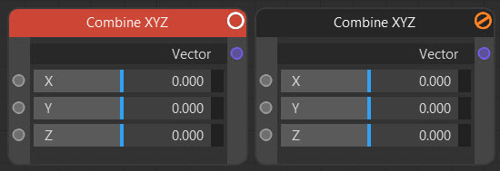
In this image the unmuted (active) node is on the left and the muted equivalent on the right.
Note: you may need to refresh the real time preview window by pausing and restarting it to see the effect of the muted node if you use the mute button.
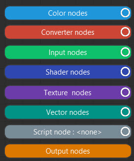
Node name and colour
You cannot alter the colour of the node title bar but note that different categories of nodes (Color, Input, etc). have different title bar colours to make it easier to find a node. Finally, you can right-click a node to display the context menu, and rename the node by selecting 'Rename Node' from the menu.
Here are the colours for the various node types:
Node groups also have colours and you can change those if desires. See the node groups page for details.
Resizing nodes
You can stretch a node horizontally by dragging on the right-hand edge of the node. Note that you cannot shrink a node below the minimum required to display its contents, nor can you stretch it vertically.
You can also double-click the node title bar to display the title bar and mute button only, plus any ports currently in use. All other ports are not shown:
Node ports (or sockets)
Cycles 4D nodes can have only input ports, only output ports, or both. Different types of ports have different colours to help you identify them more readily::
| Port Type | Colour |
|---|---|
| Shader (includes ports such as Surface, Volume, etc.) | Green |
| Color | Yellow |
| Vector | Purple |
| Numeric value | Grey |
| String | Blue |
You can hide any ports which are not being used by selecting the node then right-clicking the title bar and from the context menu choose 'Hide Unused Sockets'. To show them again, bring up the context menu then choose 'Unhide Unused Sockets'.
Making more space
Some of the nodes are quite large and occupy a lot of space in the node editor. You can reduce this by double-clicking the node title bar. It will then shrink to show only the title bar and connections, as shown in the section 'Resizing nodes' above. Alternatively, you can hide unused ports as described in the 'Node ports (or sockets)' section above.
These methods can be very useful to save space in the editor.
You can also close the node list and material settings panes by going to the 'Options' menu and unchecking both entries.
Linking nodes
This is done in the same way as Cinema's Xpresso editor. Drag with the mouse from one of the ports (or 'sockets') you want to connect to the other one. A 'rubber band' line will appear while dragging. When you get close to the second port, the line will snap to the port and the two connected ports will turn orange.
If you are dragging a connection and drag outside the visible area, the editor will automatically pan to follow the dragged connection. This makes it much easier to connect to a node which is not visible when you start to drag.
Note that certain combinations of port types are not compatible and it is not possible to connect such ports. For example, you cannot connect a BSDF output port to a Color input.
Automatic node linking
If you have two nodes linked together, you can drag and drop another node onto the link between the two. Provided that the nodes are such that their ports can be linked, the third node will be inserted into the chain automatically.
Disconnecting ports
To disconnect two ports, either:
- click and hold the input port then drag away from the port and the connecting line will disappear;
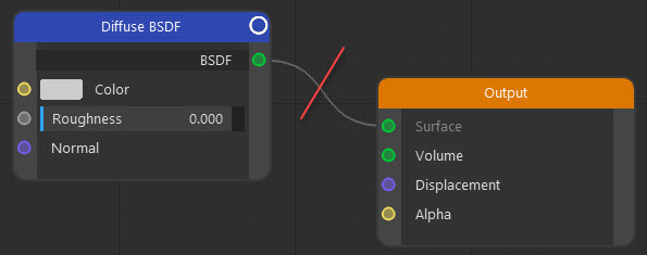
- or hold the Alt key and click and drag across the connection; a red line will appear, and when you release the mouse button the connection will be broken:
- or click and hold on one of the nodes and 'shake' it a few times (waggle the mouse left to right) to disconnect the nodes
Cycles 4D also has a feature whereby nodes can be connected automatically. If you have two nodes connected together, and you create a third node, you can drag the third node over the connecting line and Cycles 4D will automatically connect the original output node to an input port on the new node, and an output port on the new node to the original input node. If you don't like this feature, you can turn it off in the Cycles 4D Preferences.
This usually works quite well and Cycles 4D does a good job of making appropriate connections, but if it gets it wrong you can break the connections it made and make your own.
Note that you aren't restricted to connecting ports only to other ports of the same type. For example, you can connect a colour to a numeric value because Cycles 4D will simply convert the colour to a number. Sometimes such connections aren't useful - connecting a vector output to the surface input of an object material output node, for example, will simply make the material go black - but it can be a time saver in some cases to avoid doing the conversion yourself.
Shortcuts to link nodes
There are other ways to link nodes that may be more convenient in some cases. These include:
Hotkey
Select two nodes and hit the 'C' key. Cycles 4D will try to connect the two nodes together. This works best when the outport of one node is the same type as the inport of another, for example, both are Color ports or both are Vector ports.
If the two nodes have more than one identical port pair, for example they both have Color and Vector ports, only one pair will be connected. This may not be the one that you want of course, so this feature has its limitations.
Context menu
Suppose you have a node with an output Color port and you'd like to connect it to the input Color ports of two more more other nodes. Rather than make each connection individually, you can do this:
- select the nodes you want to connect to (NOT the one you want to connect from)
- on the node you want to connect from, right-click on the output port to be connected
- choose 'Connect Selected' from the menu:
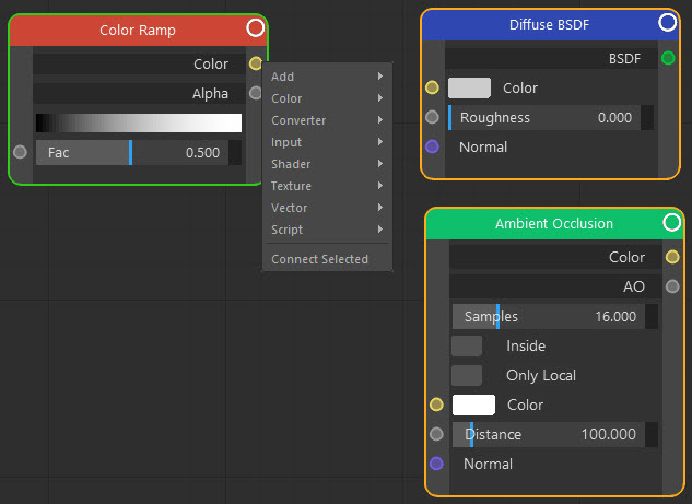
The single output port will then be simultaneously connected to the equivalent input ports of the other nodes.
This method is sometimes better than the hotkey because you can specify which output port is to be used. As explained above the hotkey may sometimes choose a pair of ports to connect which aren't the ones you wanted.
Note that only identical ports will be connected - Color to Color, Vector to Vector, etc.
Editing node settings
This topic requires detailed explanation so has a separate page dedicated to it.
Node groups
As with editing the node settings, node groups also have their own page.
Frames
If you have a complex node tree it can occupy a lot of screen space. You can reduce this by enclosing selected nodes in a frame, which can then be collapsed to reduce the space taken up. For example, suppose you have nodes arranged like this:
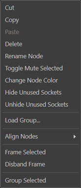
But you don't need to see all these nodes and you could use the space they occupy. If you select them all and right-click in the node editor the context menu contains the entry 'Frame Selected'.
If you choose 'Frame Selected' the three nodes you selected will all be added to a frame, like this:
This doesn't seem to have done very much but you can double-click the frame title bar to give this:
Which now takes up much less screen space (note that the frame title bar is reduced in width to avoid a long title bar occupying excessive space).
Another way to add nodes to frames is to choose 'Add->Empty Frame' from the context menu, which does exactly that - adds an empty frame to the editor. If you now select the three nodes then right-click on the frame's title bar, one option in the context menu which appears is 'Add Selected Nodes to Frame'. Click that, and the selected nodes are added to the frame. You can use this method to add more nodes to the frame at any time.
Finally, you can simply drag a node onto a frame and the node will automatically be added to the frame. Any connections it has will be preserved.
You can still edit the attributes of any node in the frame. Double-click the frame to expand it again, and now you can see and edit any of the nodes it contains.
Other frame options
You can do more with frames than this. Right-click on the title bar of a frame, and this context menu appears:
Most of these commands are described elsewhere, but note the following ones:
Toggle Mute Selected
If the frame is selected, choosing this option will mute all the nodes contained in it. Use the same option to unmute the nodes.
Add Selected Nodes to Frame
Click this option to add any selected nodes to the frame (the frame itself must not be selected when you do this, as the frame cannot add itself to itself!).
Disband Frame
Removes the frame from the node editor and shows the nodes that were contained in it again. (You can press Ctrl-F to do the same thing if the frame is selected and no other node is.)
In fact, the frame is just another node, so you can do with it more or less anything you can do with any node. You can even add a frame to another frame. It does not have any attributes of its own that you can change, though.
Pivots
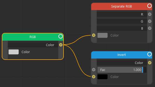
A pivot is a special node which allows you to connect two ports with a 'joint' - the pivot - in the middle. You can then move the pivot and the connections will follow with it. Here is a typical example:
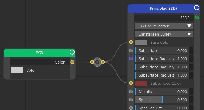
The pivot is the 'doughnut' shape between the two nodes. In this example its ports are yellow because the output port from the RGB node is a Color port, which is yellow; if the output was a Vector port, the ports would be purple.
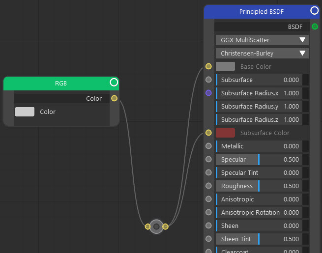
To move the pivot, click and hold on the hole in the middle (not the yellow pivot body). You can then drag it elsewhere:
Adding a pivot
To add a new pivot, right-click in the node editor and choose 'Add->Pivot'. To connect, either:
- drag the pivot over an existing connection, which will automatically remake the connection to include the pivot;
- or drag from each port to the pivot to connect it to the pivot (note: the connection area of the pivot is on the left-hand edge for incoming connections and on the right-hand edge for outgoing connections)
You can also add a new pivot to an existing connection by holding the Ctrl and Alt keys, then holding down the let mouse button and dragging the mouse over the link. This will automatically add a new pivot to the link.
Deleting a pivot
If you select the pivot and hit Delete, the pivot is deleted and the connections will be made directly between the ports. You can also click and hold a pivot and shake it, which will not delete the pivot but will break all the connections to and from it.
Editor mini-map (or global view)
With large node trees it is quite easy to lose track of all the nodes - some, perhaps many, may not be visible in the editor. You can still see where other nodes are though, with the mini-map display. This is found in the bottom-left corner of the node editor window (you can change its position in the preferences):
The blue line shows the section of the editor currently displayed in the editor window. As you zoom in the proportion of the editor area which is visible will decrease, so the box will shrink; as you zoom out the box will increase in size until it shows all the nodes in the editor.
The nodes are drawn in the colour of their node type. In the image shown, you can see that three nodes are present in the visible area of the editor. if any others are present but not visible, they will be shown outside the blue box:
The mini-map is interactive, so you can drag the blue box with the mouse to show those nodes not seen in the window.
If you don't like the mini-map display, you can turn it off and on by clicking this icon in the node editor's icon bar: ![]()