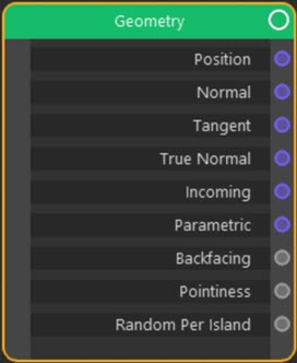
Input: Geometry
Node Interface
Overview
| Function | |
| Nearest C4D equivalent |
This node provides a variety of information about a point to be rendered on the surface of an object.
Settings
None.
Output
Position
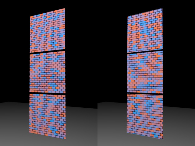
Outputs the position of the point to be rendered. Note: this is in world space, not object space, so moving the object will result in a different part of the texture being seen.
The effect of this output can be seen in these images. In the first, a Brick Texture is used to shade a Plane object in a Mograph Cloner. You can see that on the left each clone has an identical pattern texture. On the right a Geometry node with Position output has been used to ensure each clone gets a different part of the texture:
Normal
Outputs the surface normal at the point to render. Note: normal and bumps maps will affect the returned normal.
Tangent
Outputs a tangent to the surface at the point to render.
True Normal
As with Normal, but normal and bump maps are ignored.
Incoming
The output is a vector between the camera and the point to render.
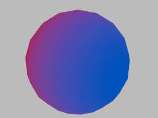
Parametric
This one is a little difficult to explain. Suppose you have a Color Ramp node whose Fac value is driven by a Gradient Texture node set to Linear. The result (on low-poly sphere) would look like this:
If you now link the Parametric output of the Geometry node to the Vector input of the Gradient Texture node, you will see this:
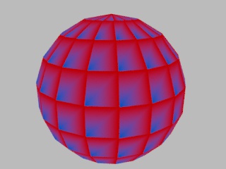
Essentially, every polygon in the sphere has its own copy of the gradient. The node tree would look like this:
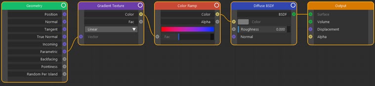
Click to enlarge image
Backfacing
Very useful output which has a value of 1.0 if a normal points away from the camera and 0.0 if it points towards the camera. You can use this to shade a faces differently depending on the direction of the normal. In this node tree, polygons with normals pointing towards the camera are shaded red, those whose normals point away are blue:
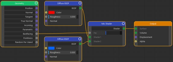
Click to enlarge image
This gives a result like this:
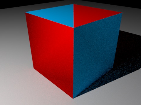
(The normals of the blue polygons were deliberately inverted to show the effect.)
Pointiness
This is a potentially very useful output which approximates a curvature shader. It measures the angle between a point to be rendered and an adjacent point and returns a value depending on the result. You can then link this value to other nodes, such as a Color Ramp node, so that the colour depends on the 'pointiness' of the surface point.
in this scene, the left-hand image is a landscape object with a plain Diffuse BSDF shader applied. In the right-hand pane, this is the node tree:
Click to enlarge image
Giving this result:
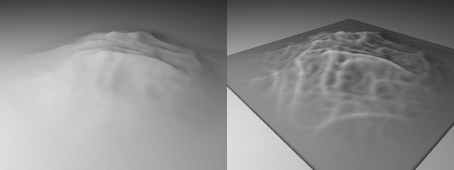
Note how the concave areas in the object become darker and the sharp, convex areas brighter.
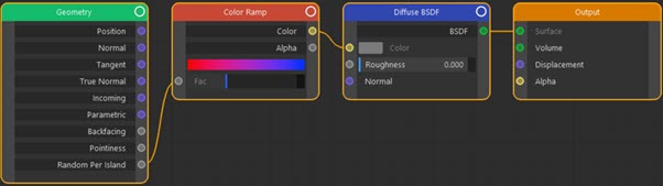
Random Per Island
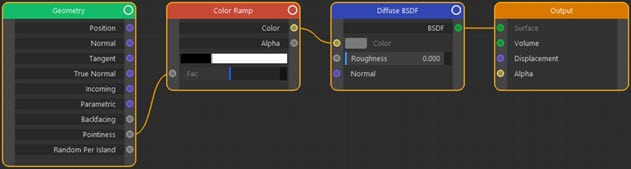
With this setting, if you have a mesh consisting of separate pieces which are not connected, each piece (or 'island') will be assigned a randomly-selected colour. In this example, a Figure primitive has been made editable then all its component parts joined to together in one mesh. However, the individual islands of polygons remain separate from one another. The result looks like this:
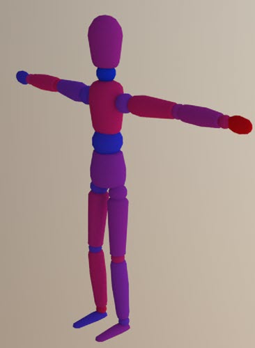
The node tree which does this is very simple:
Click to enlarge image
Node tree
Node tree
Node tree
