 mtDualGraph
 mtEdgeSpline
 mtInset
 mtPolyScale
 mtSelect
 mtShellGen
 mtSplineSample
 mtSubDivider
 mtRemesh
 Global Settings
 Sphere
 Tree
Tree Koch
Koch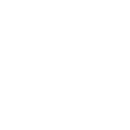 Dragon
 Fern
Fern Fibonacci
 mtShortestPath
mtShortestPath generates splines by finding the shortest path between two object points along the polygon edges. Spline Growth settings enable organic animation effects.
Overview Video
TerraformFX terrain as a child of mtShortestPath in the Points Mode setting of Random Selection.
Object
Object Properties
Points Mode
There are two modes for defining which object vertices mtShortestPath will use as its start and end points: Random Selection - the default mode, Random Selection and Fixed Selection.
Random Selection
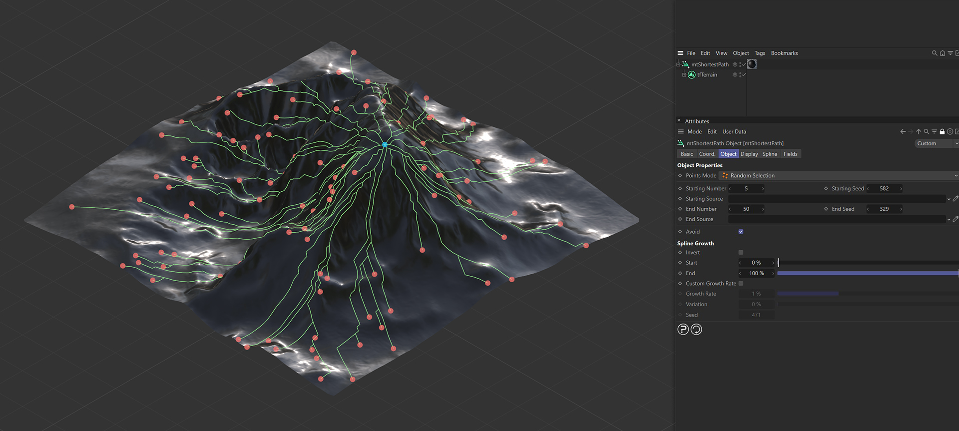
Random start and end points will be chosen from the object vertices.
Start and end points, in Random Selection mode, with the shortest path generated between them.
Starting Number
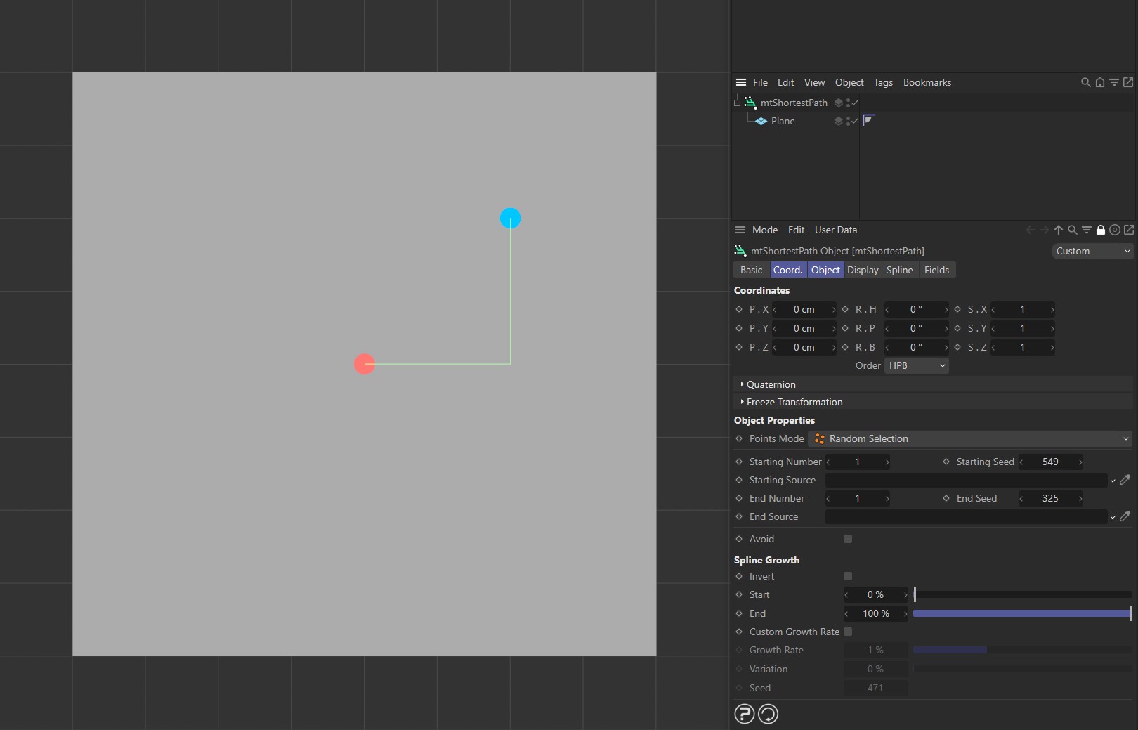
You can define how many starting points mtShortestPath will use. Every start point will draw a path to every end point.
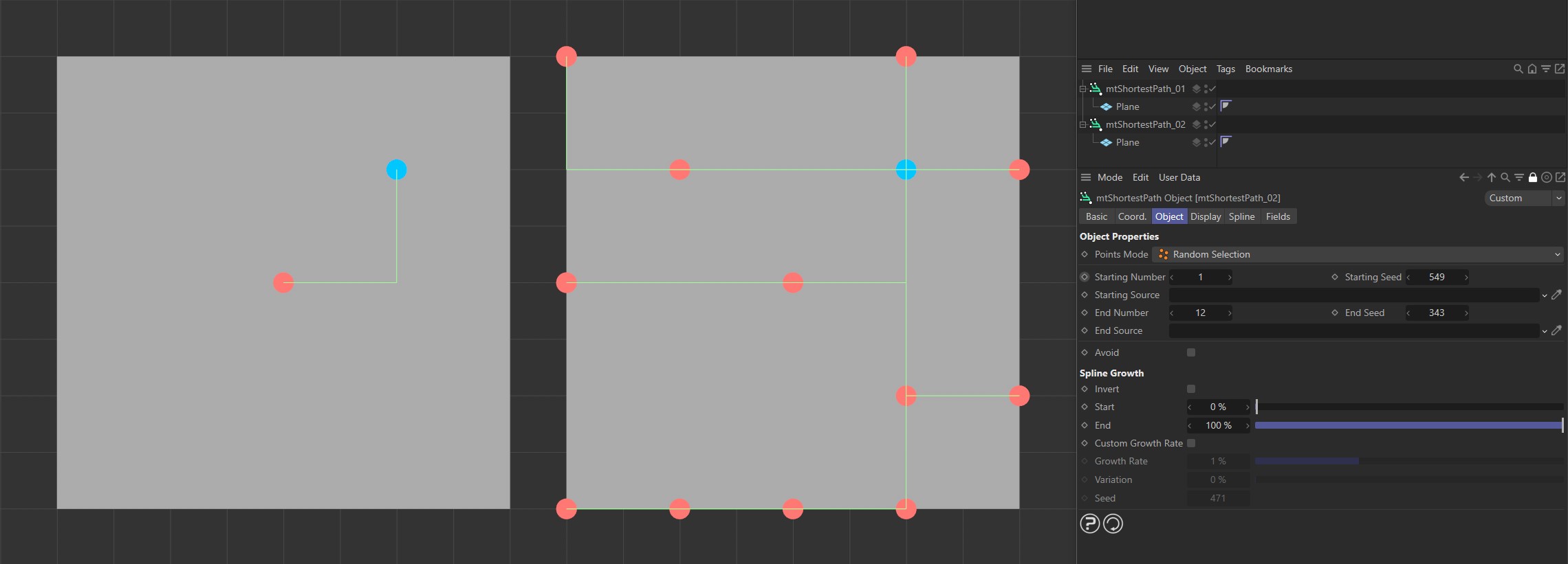
Random Selection mode, with Display tab options enabled. The Plane on the left has a Starting Number of 1 and the Plane on the right has a Starting Number of 12.
Starting Seed
Change this value to use different randomly-chosen start points.
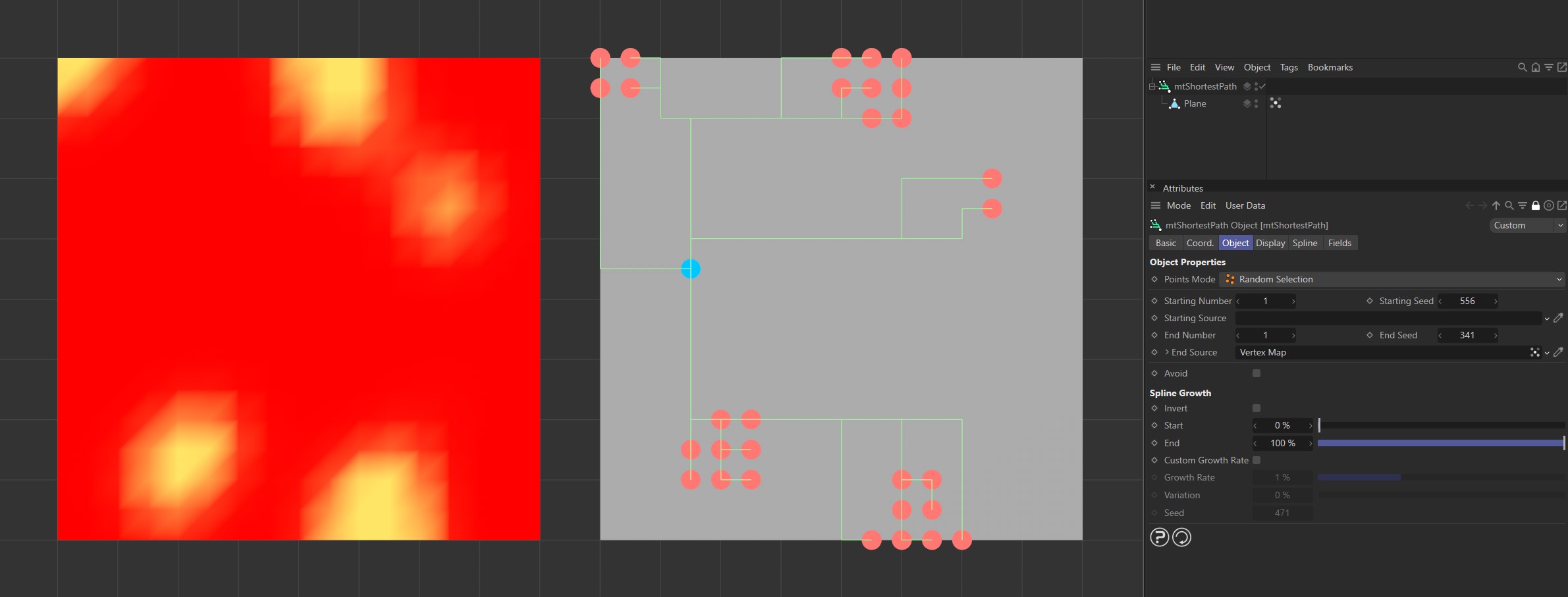
Starting Source
Instead of randomly selecting start points, you can use selection tags or a vertex map to define them. Drag the tag from the Object Manager into the Starting Source link field.
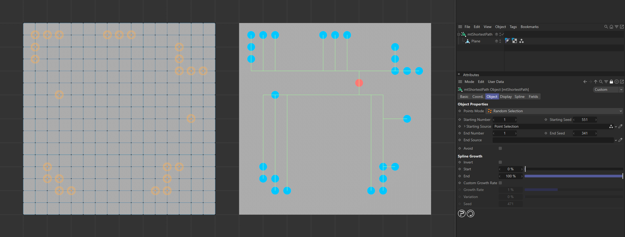
The Plane on the left has a polygon selection tag, which is displayed in the viewport. An identical Plane is on the right, as a child of a mtShortestPath, driving the start point positions.
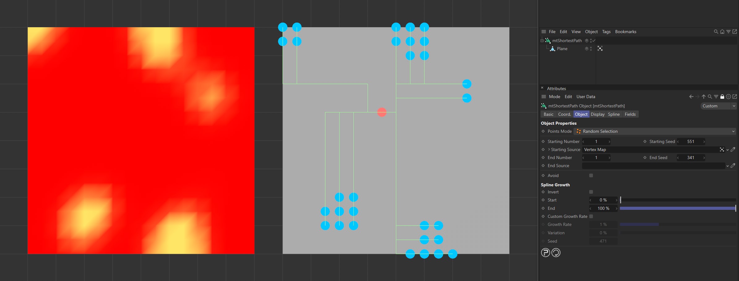
The Plane on the left has a vertex map, which is displayed in the viewport. An identical Plane is on the right, as a child of a mtShortestPath. The vertex weights are driving the start point positions.
End Number
Define how many end points mtShortestPath will use.
The Plane on the left has an End Number of 1 and the Plane on the right has an End Number of 12.
End Seed
Change this value to use different randomly chosen end points.
End Source
You can also use vertex map or selection tags to define the end points. Drag the tag from the Object Manager into the End Source link field.
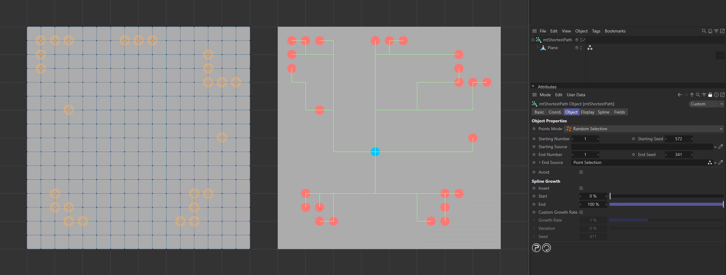
The Plane on the left has a polygon selection tag, which is displayed in the viewport. An identical Plane is on the right, as a child of a mtShortestPath, driving the end point positions.
The Plane on the left has a vertex map, which is displayed in the viewport. An identical Plane is on the right, as a child of a mtShortestPath. The vertex weights are driving the end point positions.
Fixed Selection
Fixed Selection only allows defined point selections, rather than randomly chosen points. You can use vertex map or selection tags to define the start and end points.
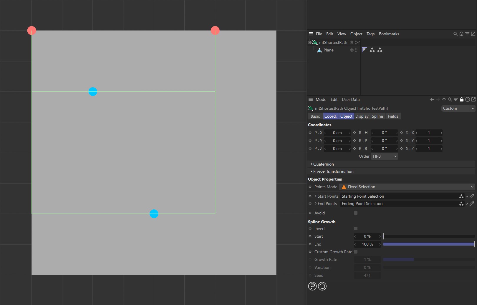
Defined start and end points in Fixed Selection mode, with the shortest path generated between them.
Start Points
Drag the vertex map, or selection tag, from the Object Manager into the Start Points link field.
End Points
Drag the vertex map, or selection tag, from the Object Manager into the End Points link field.
Avoid
Some paths from start to end points may intersect. With Avoid enabled, intersecting paths will not be generated.
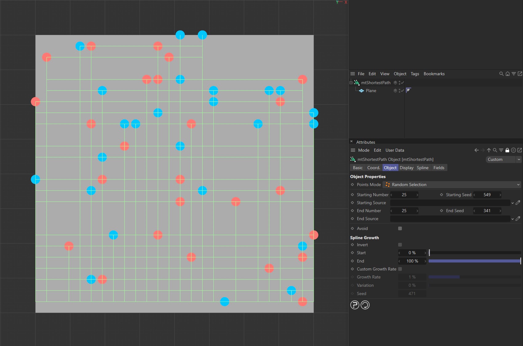
Avoid disabled.
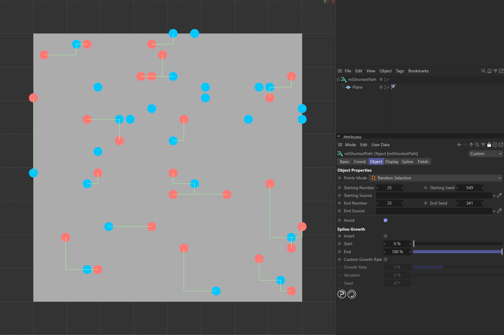
Avoid enabled.
Spline Growth
Use these settings to alter the length of the generated splines and animate growth effects.
An animated demonstration showing use of the Start and End sliders in the Spline Growth settings.
Invert
You can invert the spline growth so that it begins at the end points and grows towards the start points.
Start
You can adjust the length of the paths by changing its start point. This can be animated for growth effects.
End
You can also adjust the length of the spline by changing its end point. This too can be animated for growth effects.
Custom Growth Rate
You can set the spline to automatically grow over time.
Video demonstrating activation of Custom Growth Rate and resulting animation, with and without the Variation option.
Growth Rate
This is the rate at which a path will grow per frame. It is a percentage of its overall length. Therefore, at 1%, it will take 100 frames to grow to full length.
Variation
You can add variation to the Growth Rate setting to prevent paths from reaching their end points at the same time.
Seed
Change this value for a different variation pattern.
Display
Show Start and End Points
Enable this to display the start and end points in the viewport.
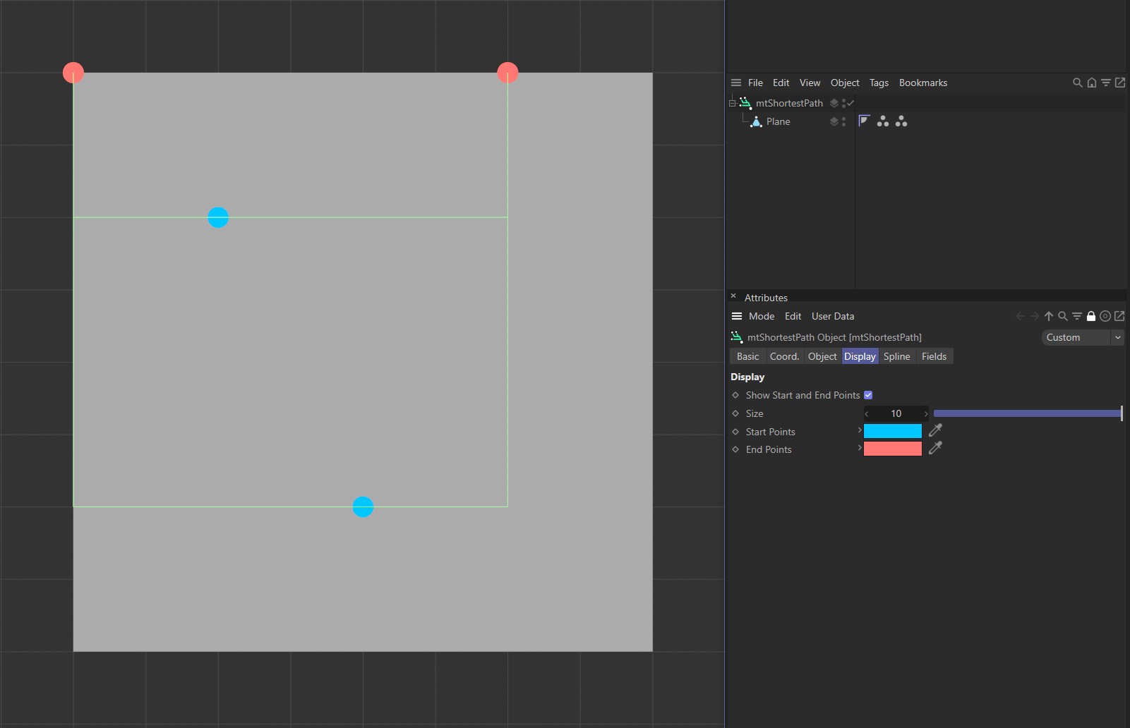
Display tab settings.
Size
Adjusts the size of the displayed points.
Start Points
Use the color picker to choose a custom color for the start points.
End Points
Use the color picker to choose a custom color for the end points.
Spline
Type
Choose from a Linear, Cubic, Akima, B-Spline or Bezier spline Type.
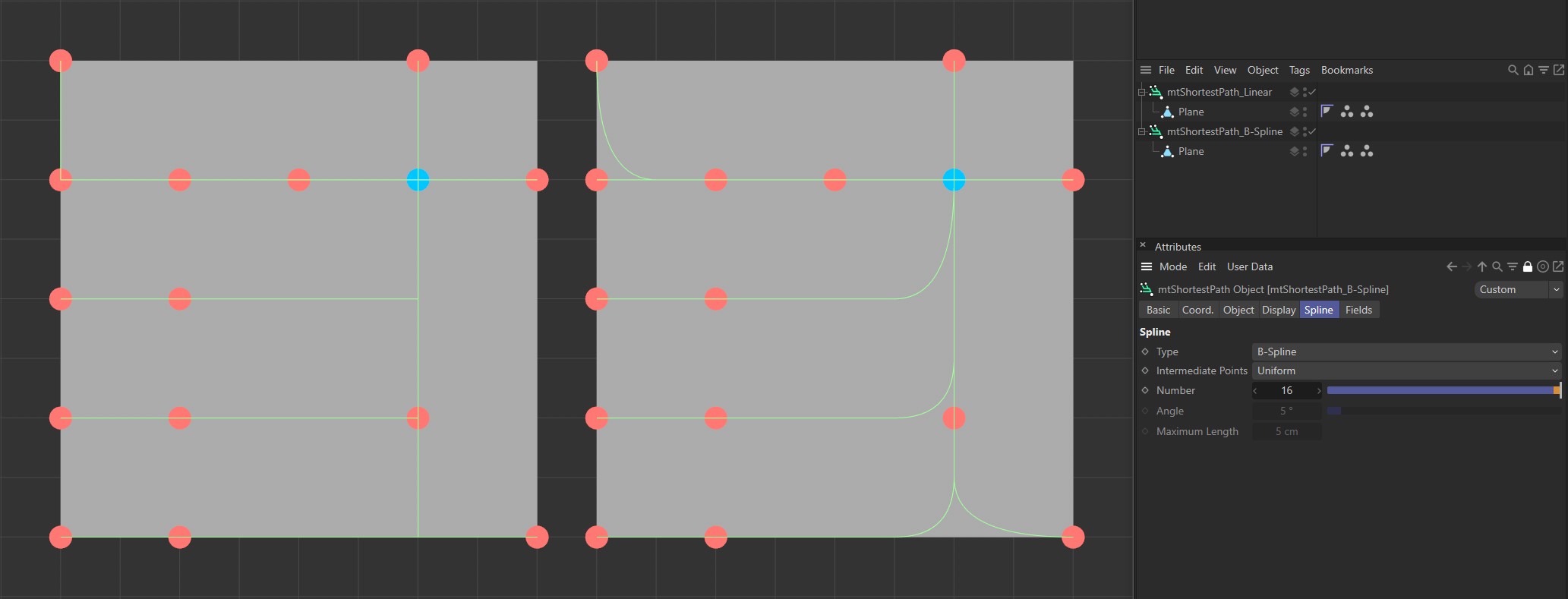
Different options for spline Type setting, with the left set at Linear and the right at B-Spline.
Close Spline
This will create a closed spline by connecting the first and last spline points.
Intermediate Points
You can choose how intermediate points are generated from the usual options.
Number
In Natural and Uniform modes, use this field to set the number of intermediate points.
Angle
In Adaptive and Subdivided modes, use this angle threshold to limit the generation of intermediate points on curved edges.
Maximum Length
In Subdivided mode, use this length threshold to limit the generation of intermediate points on straight edges.
Fields
You can use the Fields options to control where mtShortestPath operates.
Animation demonstrating use of the Spherical Field.