 mtDualGraph
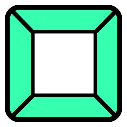 mtInset
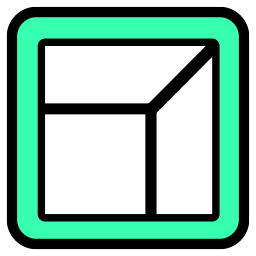 mtPolyScale
 mtSelect
 mtShellGen
 mtShortestPath
 mtSplineSample
 mtSubDivider
 mtRemesh
 Global Settings
 Sphere
 Tree
Tree Koch
Koch Dragon
 Fern
Fern Fibonacci
 mtEdgeSpline
mtEdgeSpline generates custom splines from the base geometry.
Overview Video
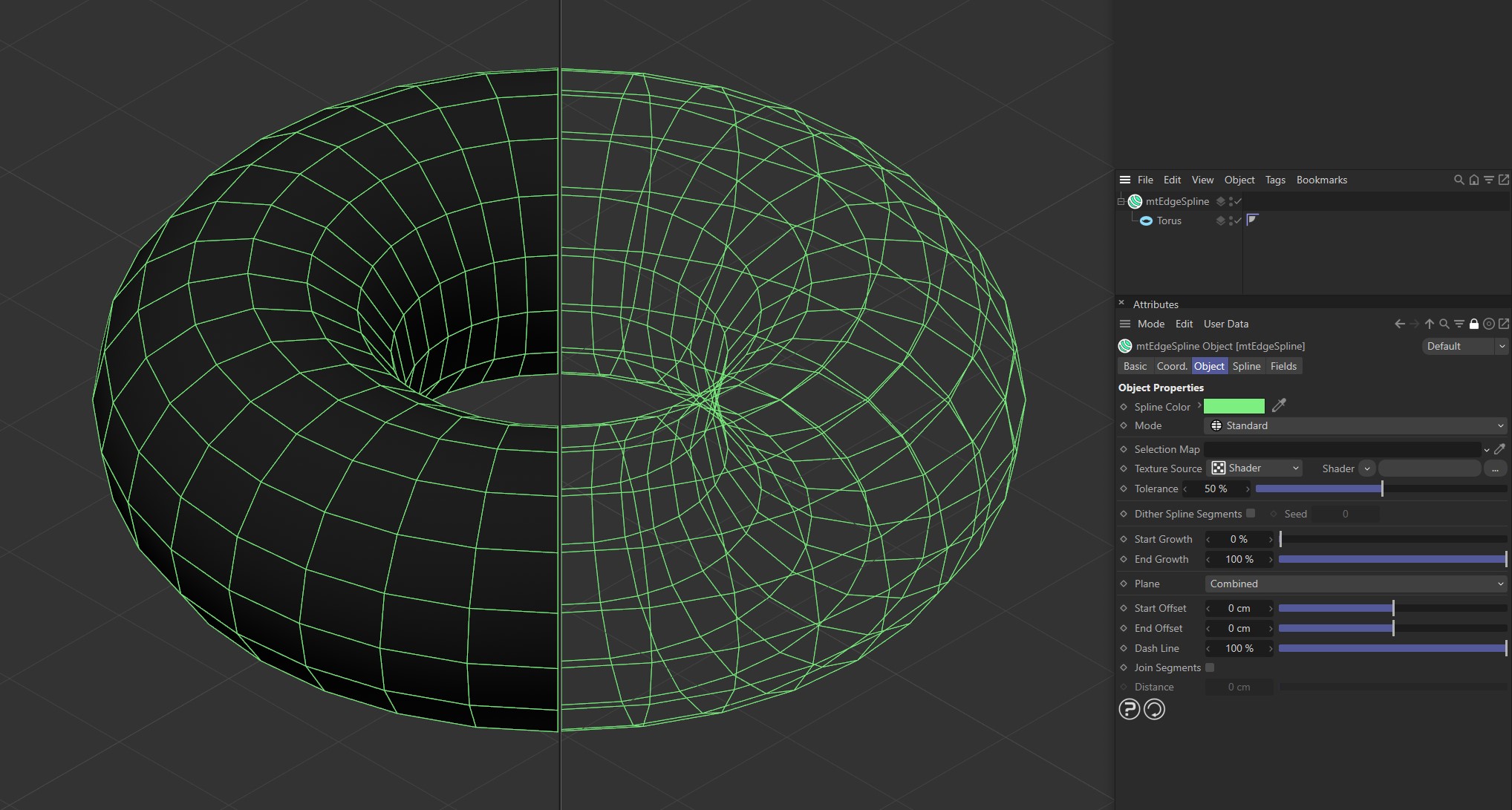
TTorus as a child of mtEdgeSpline, with Mode set as Standard.
Object
Object Properties
Spline Color
You can choose the generated spline color using the color picker.
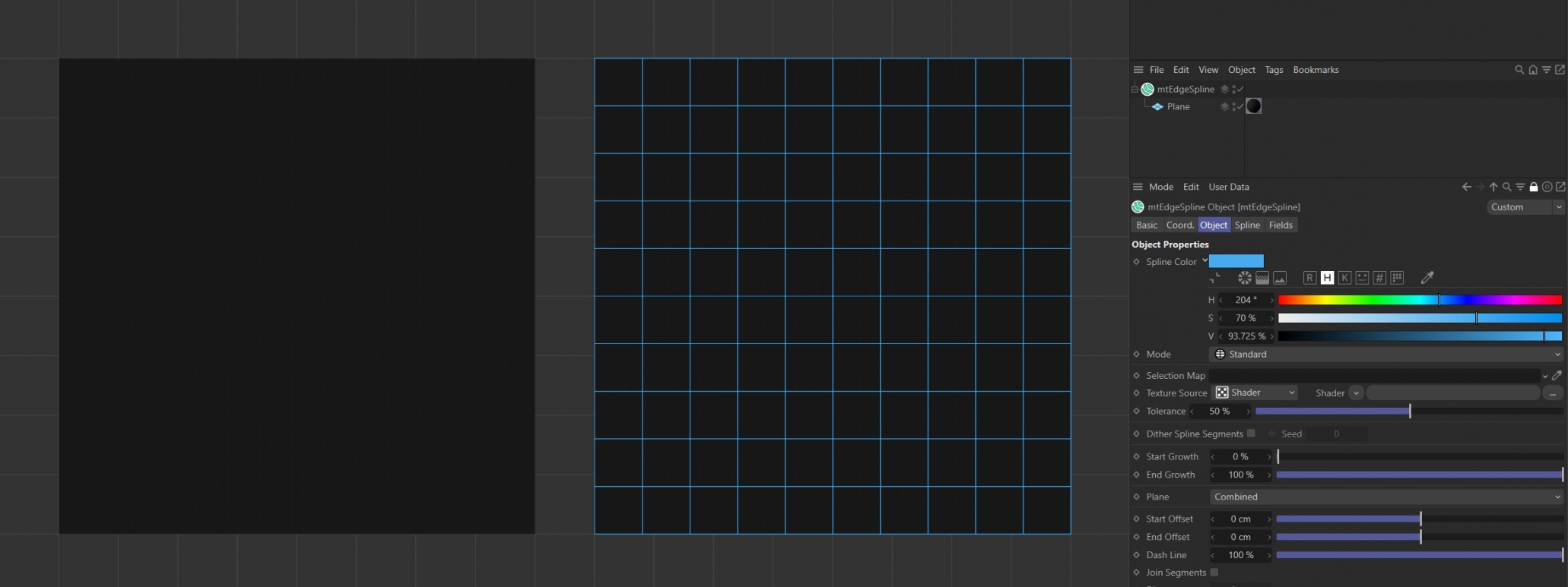
Spline Color has been set to blue for the Plane on the right.
Mode
There are five different spline types to choose from.
Standard
Edges are generated based on the existing mesh geometry.
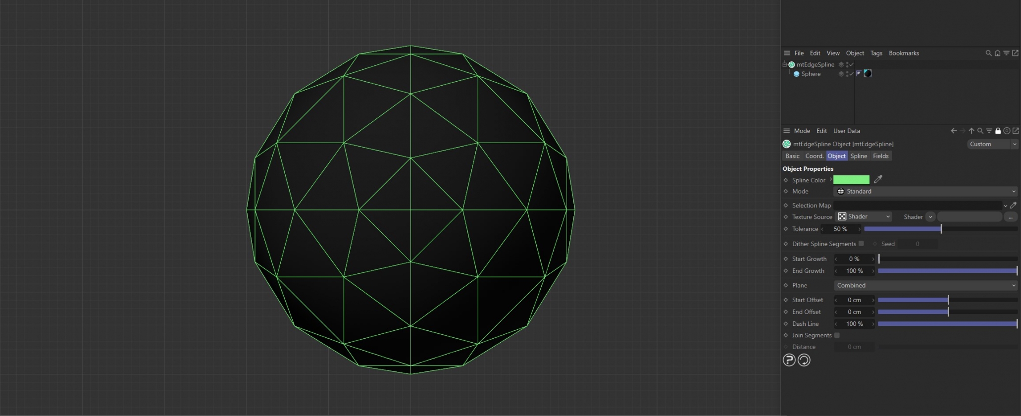
The mtEdgeSpline Mode is set to Standard for this Sphere. All of the original base mesh edges are being used to generate the spline.
Curvature
Splines are generated based on the curvature of the geometry. Use the Curvature Angle slider to set the threshold.
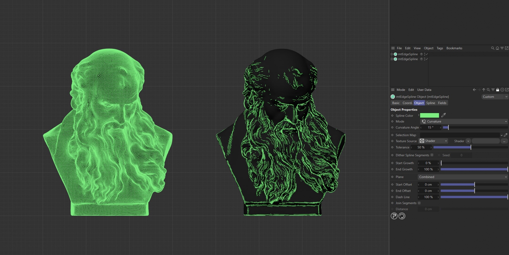
mtEdgeSpline generator Mode for both set to Curvature. The left generator has a Curvature Angle of 0 (zero) degrees. The right generator has a Curvature Angle of 16 degrees.
Contour
Evenly-spaced contour splines are generated. Use the Contour Slices setting to adjust the amount.
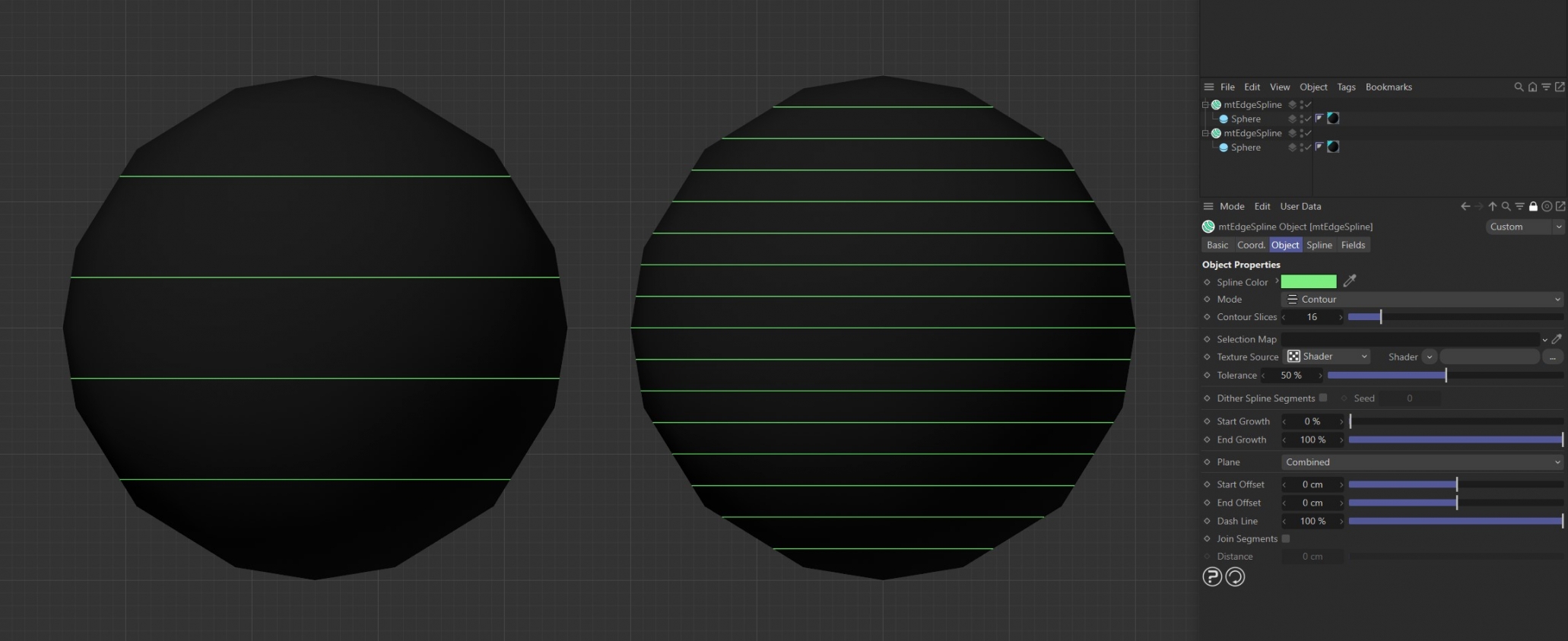
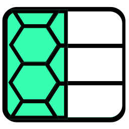
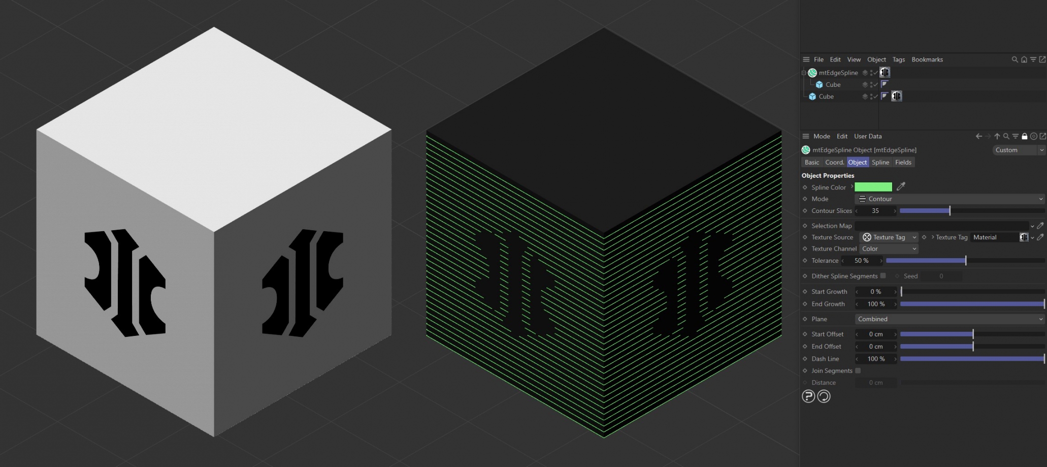
mtEdgeSpline Mode is set to Contour. The left generator has Contour Slices set to 5 and the right generator has Contour Slices set to 16.
Outline
Splines are generated based on the object silhouette. This is dependent on the viewing angle, so splines will behave dynamically with moving cameras.
With an Outline Angle of 0 (zero) degrees, splines are restricted to the silhouette. You can create thicker outlines and shading effects by increasing the Outline Angle value.
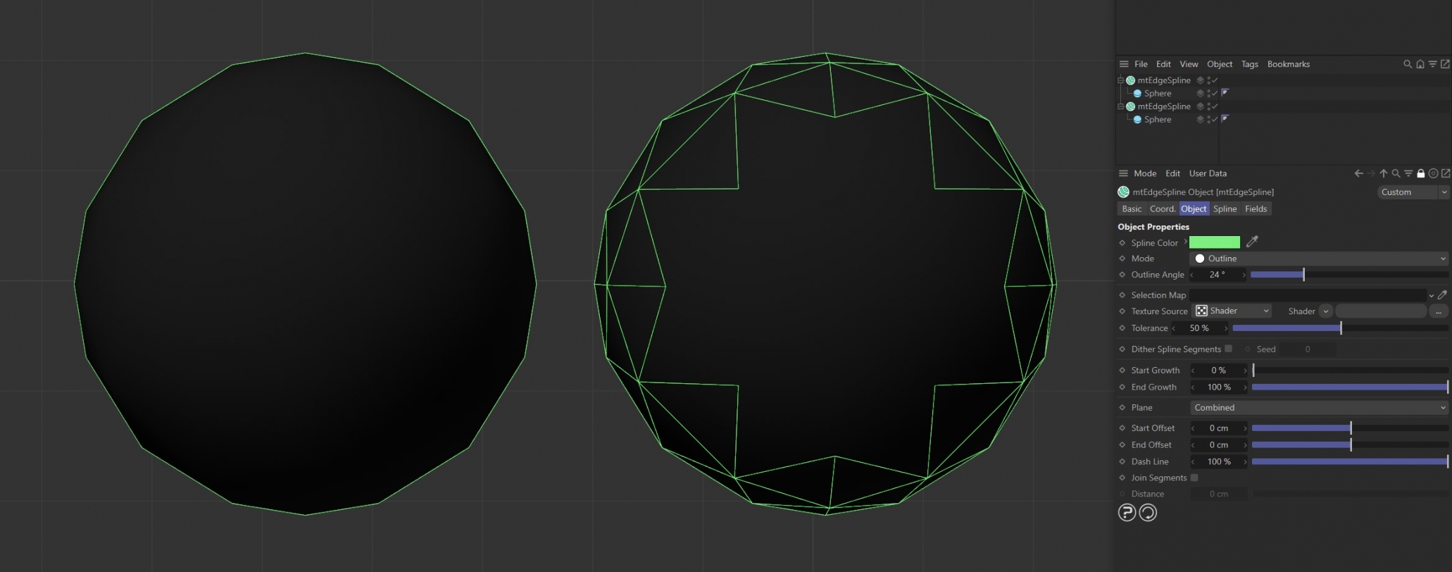
Both mtEdgeSpline generators Mode setting is Outline. The left generator has an Outline Angle of 0 (zero) degrees. The right generator has an Outline Angle of 24 degrees.
Intersection
Splines are generated where the surfaces of objects intersect. Drag objects, that you want to intersect the base geometry, into the link field.
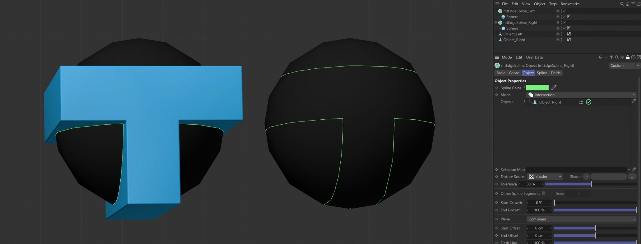
Both mtEdgeSpline generator object Mode set to Intersection, both with identical intersecting objects. The intersecting object on the left is visible and we can see the resulting generated spline on the right.
Selection Map
You can use a vertex map or selection tags to define where splines are generated. Drag the tag from the Object Manager into the Selection Map link field.
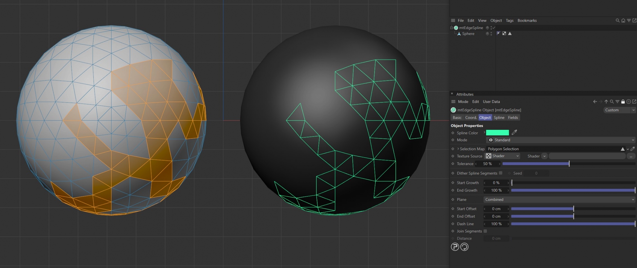
The Sphere on the left has a polygon selection tag, which is displayed in the viewport. An identical Sphere is on the right, as a child of a mtEdgeSpline, driving the generated edge spline.
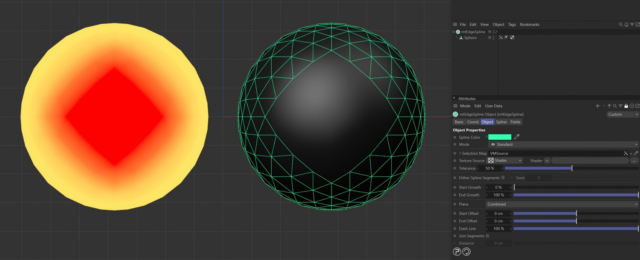
The Sphere on the left has a vertex map, which is displayed in the viewport. An identical Sphere is on the right, as a child of a mtEdgeSpline. The vertex weights are driving the generated spline setting.
Texture Source
You can use shaders, images and even animated video sequences to control where splines are generated. There are two options: Shader and Texture Tag. Both use color value to define which areas are selected.
Shader
Use the Shader drop-down arrow to select an image, sequence or shader.
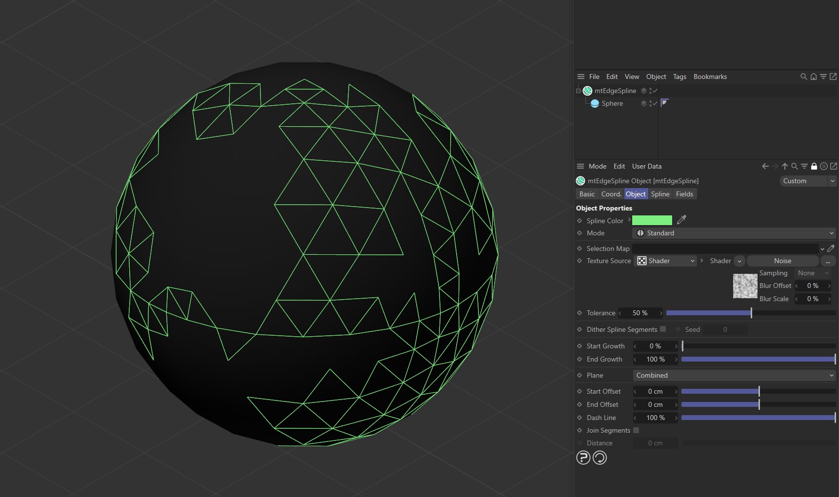
The Noise shader with mtEdgeSpline is driving the generated spline setting on this Sphere.
Texture Tag
This mode requires a Cinema4D material. Place the material on the mtEdgeSpline and you will see a texture tag appear alongside it in the Object Manager. Drag this texture tag into the link field.
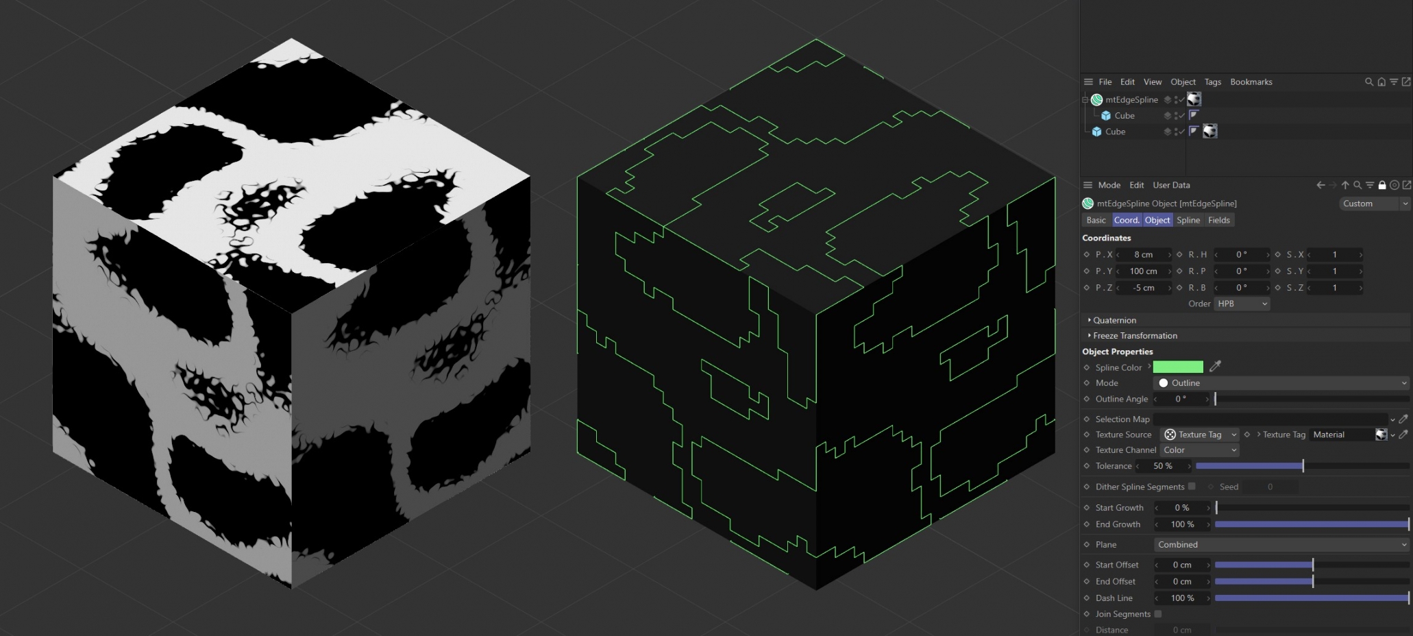
Noise shader with mtEdgeSpline Mode set to Outline, with Outline Angle at 0 (zero) degrees.
Bitmap with mtEdgeSpline Mode set to Contour.
Animated video sequence driving the generation of splines with Mode set to Intersection.
Use the Texture Channel pull-down to select which material channel you wish to reference. This is set to Color by default.
Tolerance
Use the Tolerance slider to adjust the point at which splines are generated.
Lower tolerance values will allow darker areas to be included.
Higher tolerance values will allow only lighter areas to be included.
Illustrating the Tolerance slider, which is driven by the Noise shader.
Dither Spline Segments
When using a Texture Source you are able to create a feathered edge effect by dithering the spline segments.
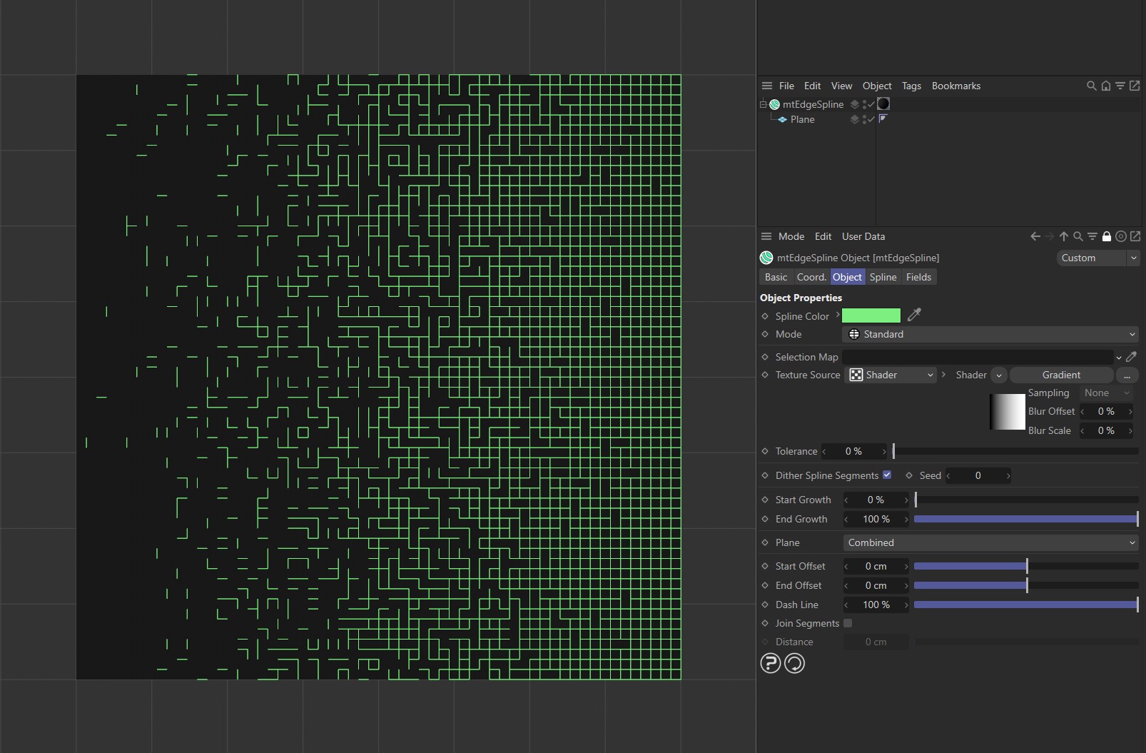
Dither Spline Segments enabled with mtEdgeSpline, driven by a Gradient shader.
Seed
Change the Seed value to generate a new random dither.
Start Growth
You can adjust the length of the spline by changing its start point.
End Growth
You can also adjust the length of the spline by changing its end point.
Sequence with mtEdgeSpline, demonstrating the Start Growth and End Growth sliders.
Plane
Combined
Horizontal (U) and Vertical (V) splines are both generated.
U
Only horizontal splines are generated.
V
Only vertical splines are generated.
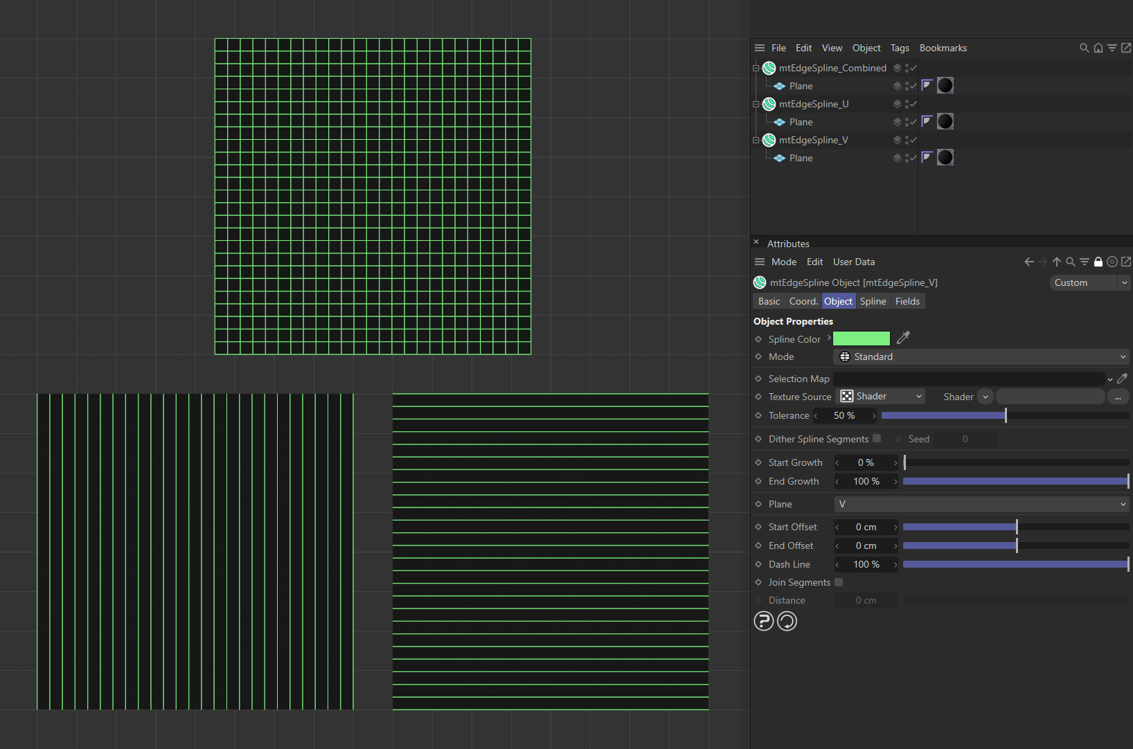
In this image the first plane, at the top, has Plane set to Combined. As a result, both horizontal and vertical lines are generated. On the lower left, the Plane setting is V. Here, only vertical lines are being generated. On the lower right, the Plane setting is U and only horizontal lines are being generated.
Start Offset
Offset the start point of each spline segment.
End Offset
Offset the end point of each spline segment.
Video sequence, with mtEdgeSpline, demonstrating the Start Offset and End Offset sliders.
Dash Line
Lower this slider from its default value of 100% to create a Dash Line effect.
Video sequence with mtEdgeSpline demonstrating the Dash Line slider.
Join Segments
mtEdgeSpline creates multiple segment splines. You can join these segments by activating this setting.
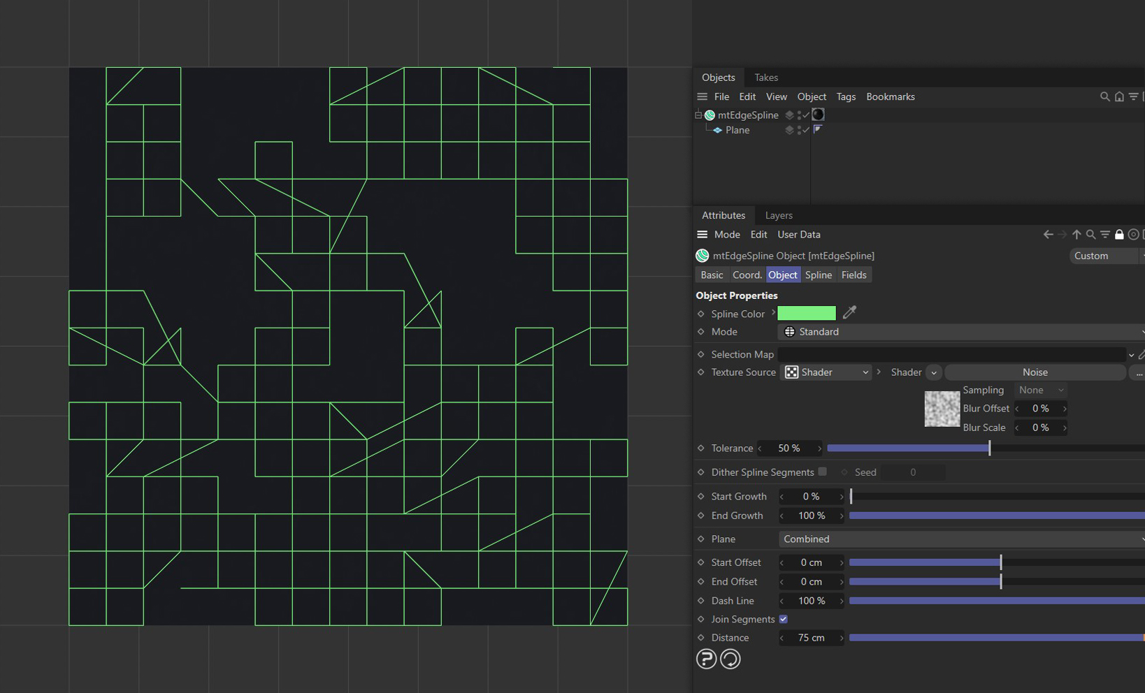
Join Segments, enabled in mtEdgeSpline, joining up segment splines.
Distance
Segments will only be joined if they are within this Distance setting.
Spline
Type
Choose from Linear, Cubic, Akima, B-Spline or Bezier spline types.
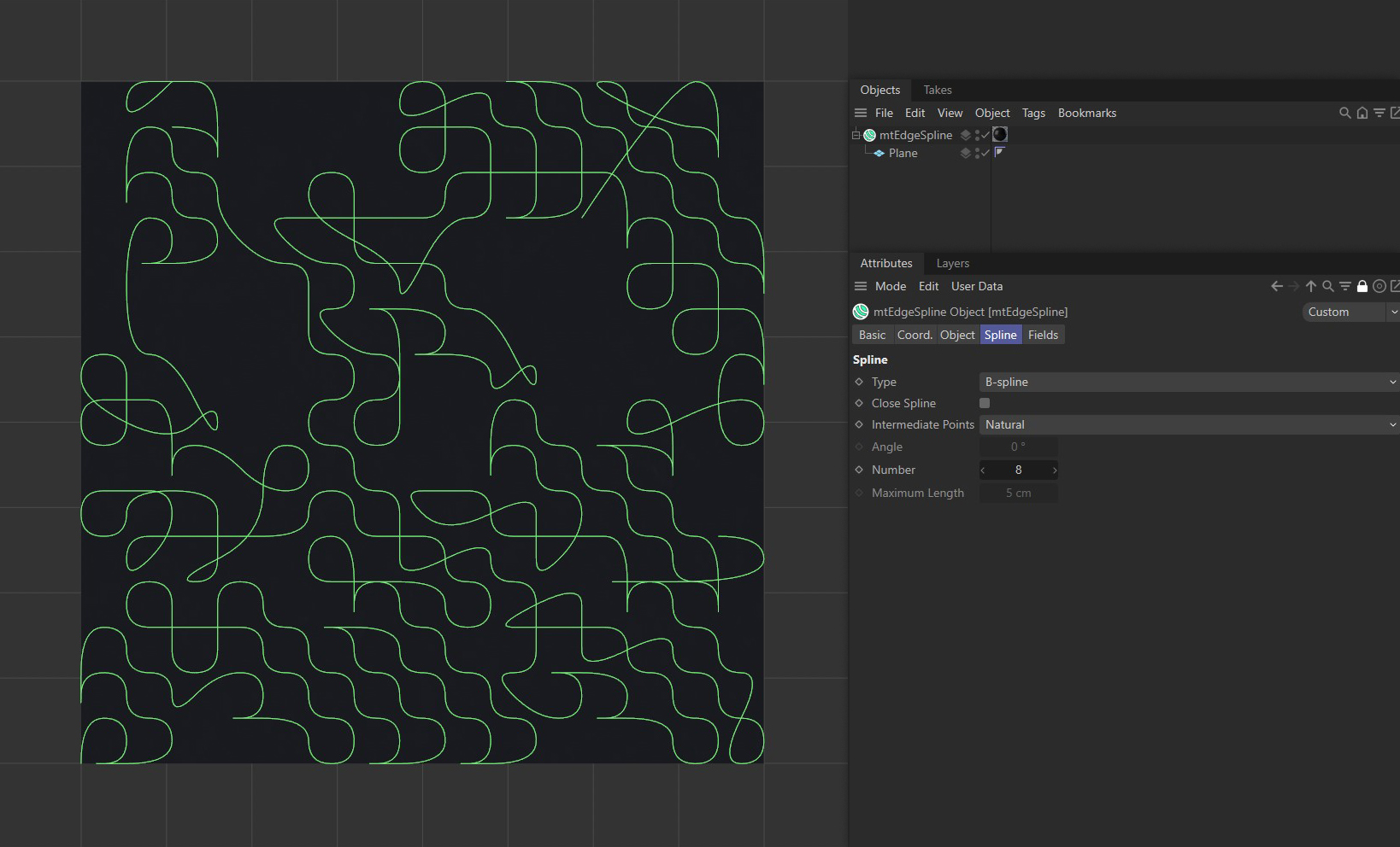
mtEdgeSpline set to B-spline Type.
Close Spline
This will create a closed spline by connecting the start and end points.
Intermediate Points
You can choose how intermediate points are generated from the usual options.
Number
In Natural and Uniform modes, use this field to set the number of intermediate points.
Angle
In Adaptive and Subdivided modes, use this Angle threshold setting to control the generation of intermediate points on curved edges.
Maximum Length
In Subdivided mode, use this length threshold to limit the generation of intermediate points on straight edges.
Fields
You can use the Fields options to control where mtEdgeSpline operates.
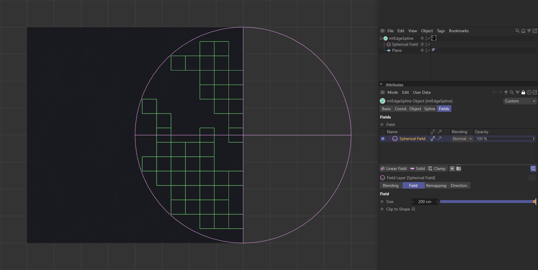
mtEdgeSpline with a Spherical Field driving the spline generation.