 mtDualGraph
 mtEdgeSpline
 mtPolyScale
 mtSelect
 mtShellGen
 mtShortestPath
 mtSplineSample
 mtSubDivider
 mtRemesh
 Global Settings
 Sphere
 Tree
Tree Koch
Koch Dragon
 Fern
Fern Fibonacci
 mtInset
mtInset generates inner extrudes from the faces of your base geometry.
Overview Video
Additional options available from Update Build No. 131
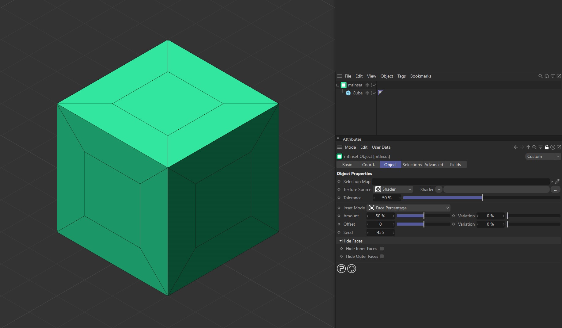
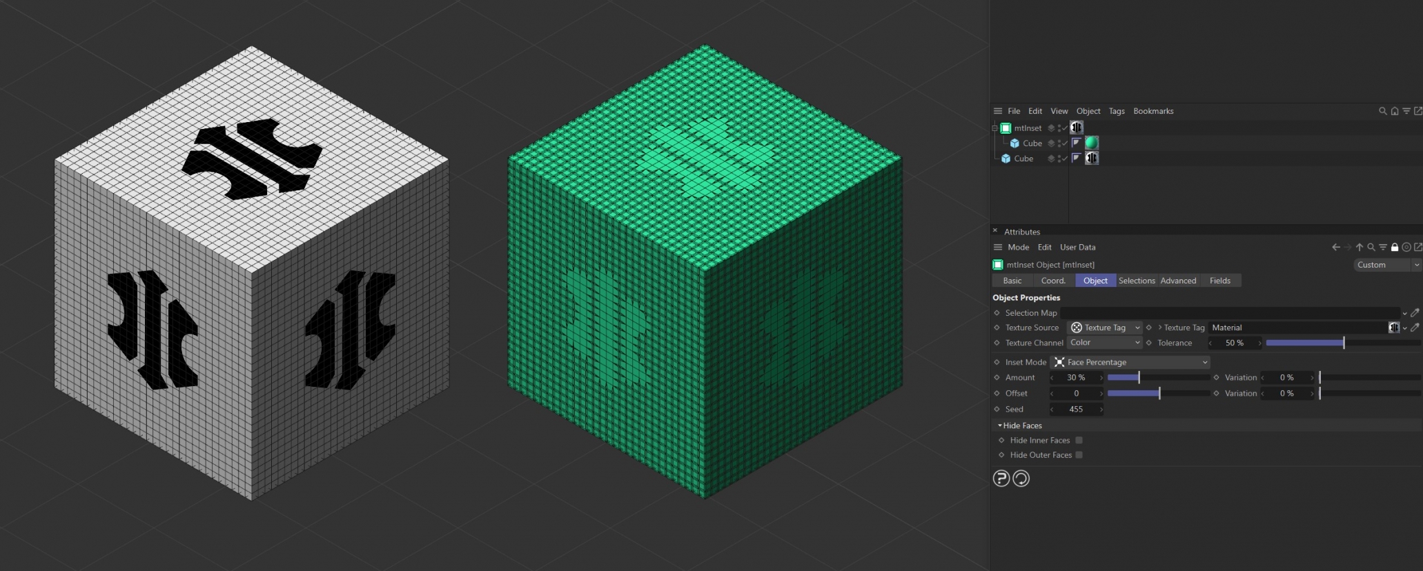
Cube as a child of mtInset, with an Inset Mode of Face Percentage and an Amount setting of 50%.
Object
Object Properties
Selection Map
You can use a vertex map or selection tags to define where insets are generated. Drag the tag from the Object Manager into the Selection Map link field.
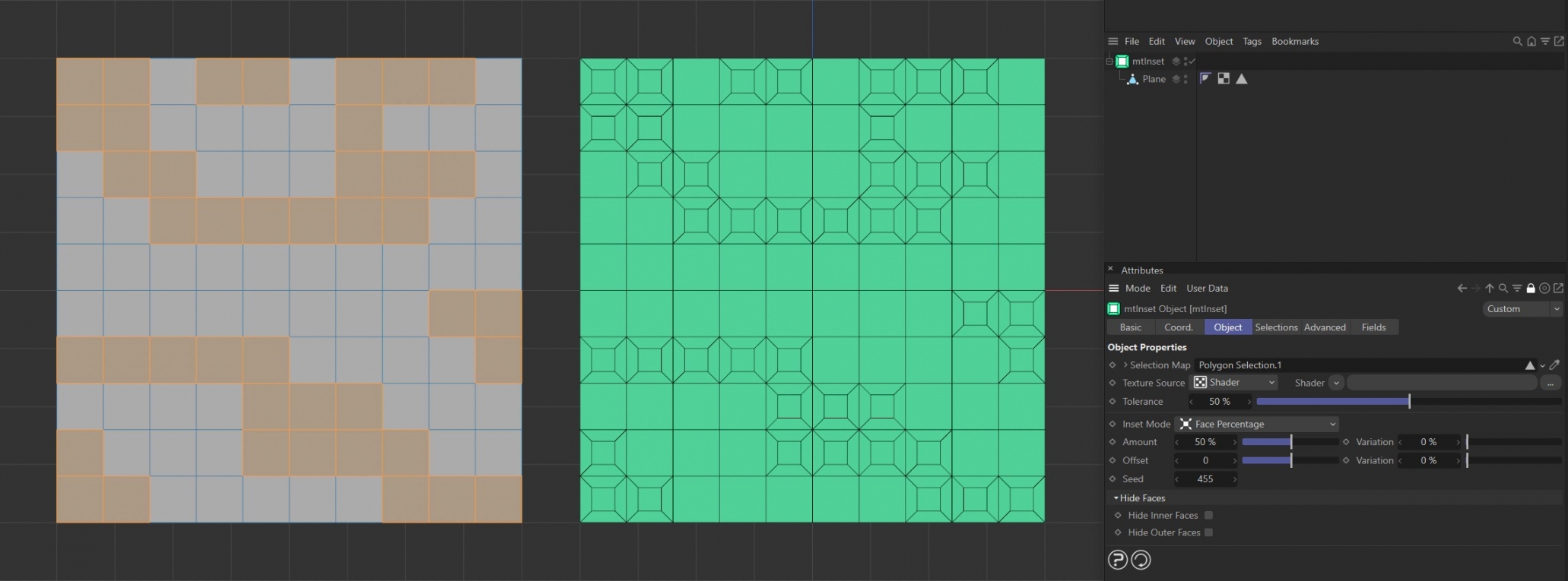
The Plane on the left has a polygon selection tag, which is displayed in the viewport. An identical Plane is on the right, as a child of a mtInset, driving where insets are generated.
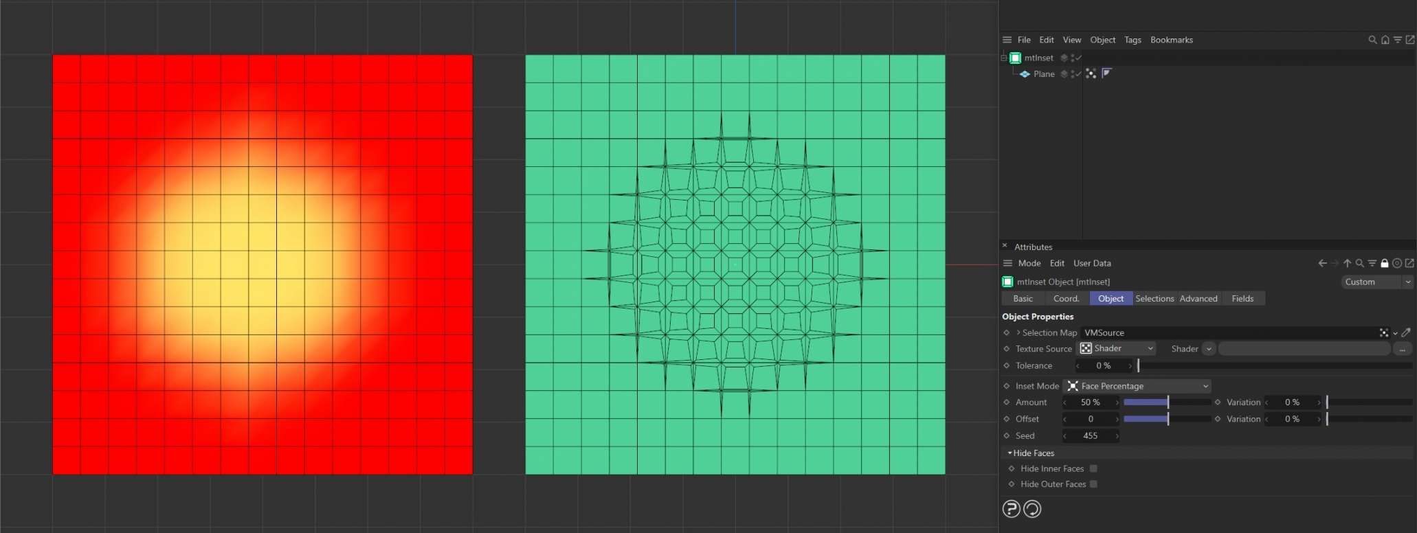
The Plane on the left has a vertex map, which is displayed in the viewport. An identical Plane is on the right, as a child of a mtInset. The vertex weights are driving the generation of insets.
Texture Source
You can use shaders, images and even animated video sequences to control where insets are generated. There are two options: Shader and Texture Tag. Both use color value to define which areas are affected.
Texture
This mode requires a Cinema4D material. Place the material on the mtSelect and you will see a texture tag appear alongside it in the Object Manager. Drag this texture tag into the Texture Tag link field.
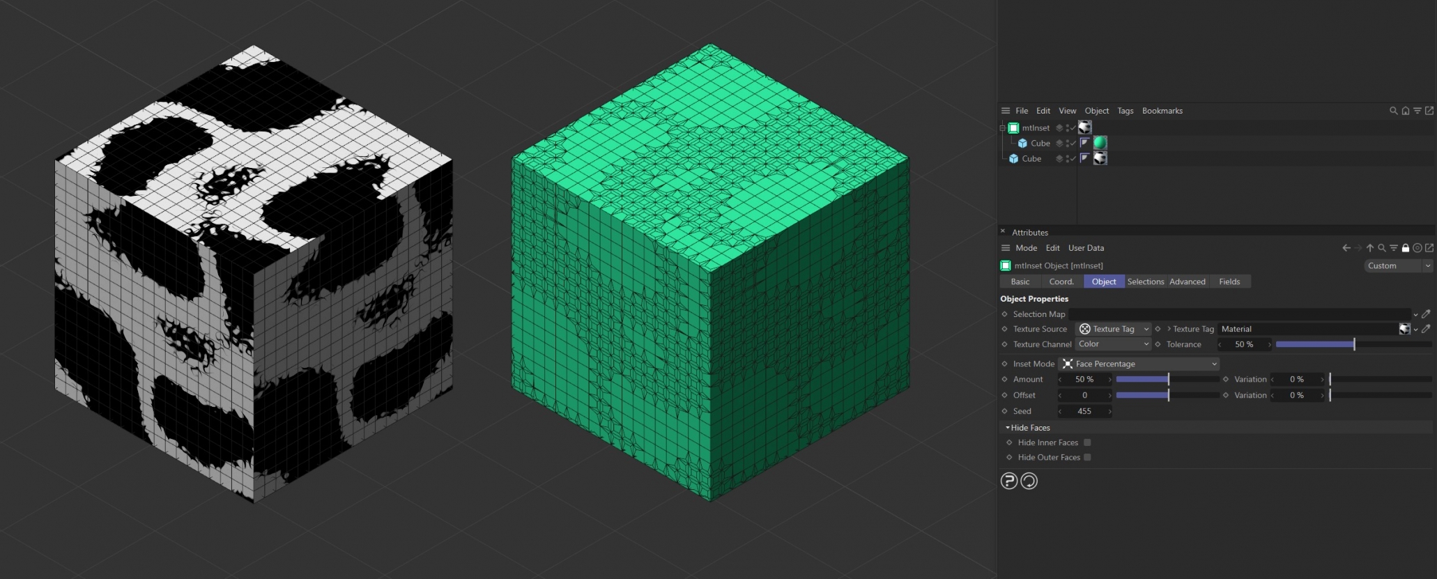
Texture Source set to Texture Tag, with the Noise shader material on the left driving the inset generation on the right-hand Cube.
Texture Source set to Texture Tag, with the bitmap material on the left driving the inset generation on the right-hand Cube.
Animated video sequence driving the generation of insets on the right-hand Cube.
Texture Channel
Use the Texture Channel pull-down to select which material channel you wish to reference. This is set to Color, by default.
Shader
Use the Shader drop-down to select an image, sequence or shader.
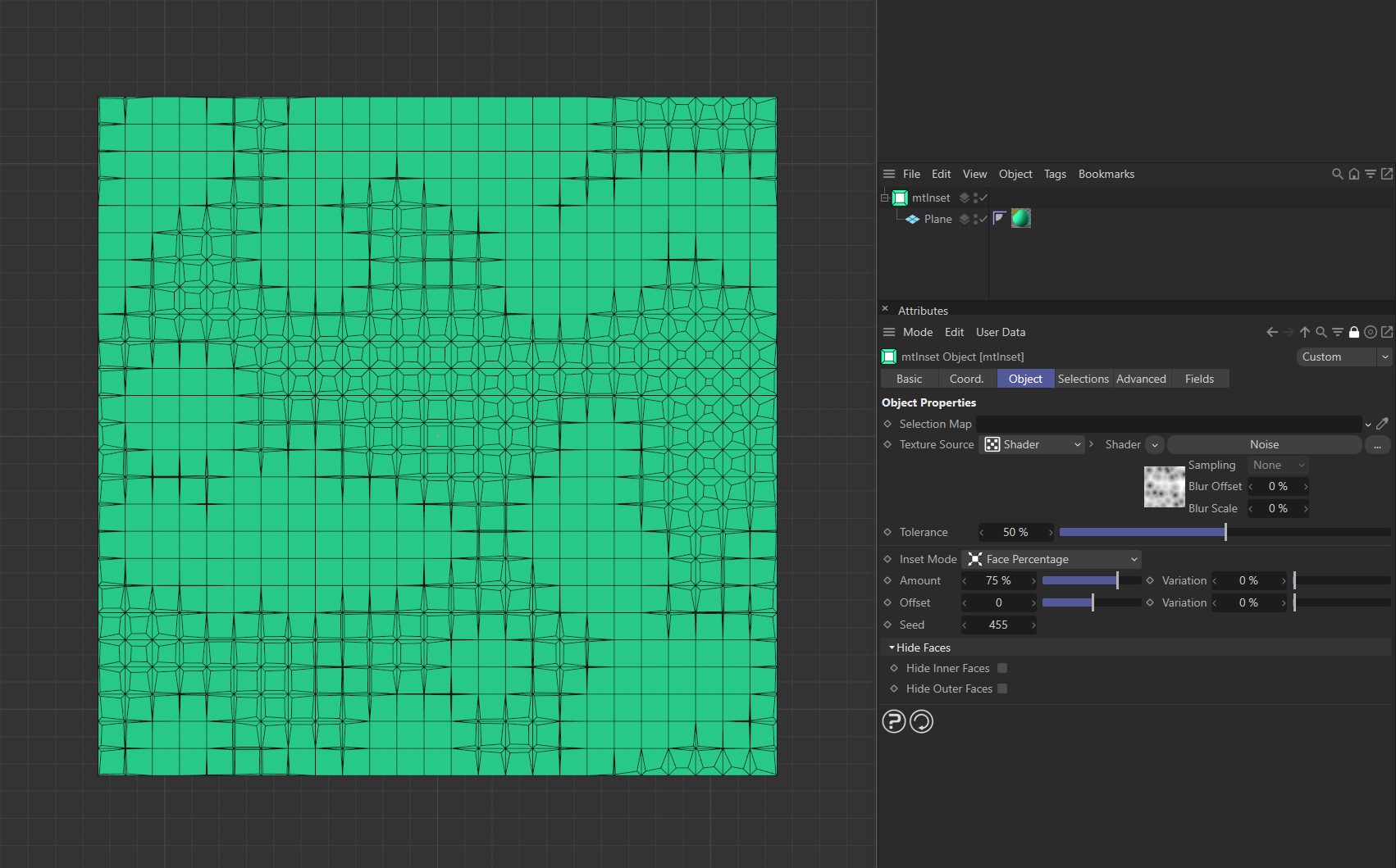
Texture Source set as Shader, with inset generation being driven by the Noise shader.
Tolerance
Use the Tolerance slider to adjust the point at which insets are made.
Lower tolerance values will allow insets to be generated in darker areas.
Higher tolerance values will allow insets to be generated in lighter areas.
Demonstration of the effects of the Tolerance slider with a Noise shader.
Inset Mode
There are two options to control the size of your insets: Face Percentage and Fixed Length.
Face Percentage
The size of the inner extrude is set using a percentage of the original face. Therefore, smaller polygons will have smaller insets than larger polygons.

The Plane on the left has Inset Mode set as Face Percentage with an Amount value of 20%. The Plane on the right is the same except the Amount value is increased to 50%.
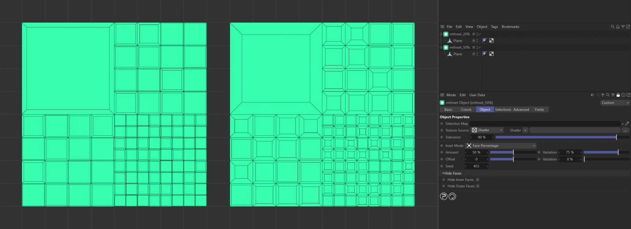
In this example, the two generators have different inset Amount settings, but both have a Variation setting of 75%.
Fixed Length
The size of the inner extrude is set using a fixed length. In this mode all insets will be the same, irrespective of polygon size.
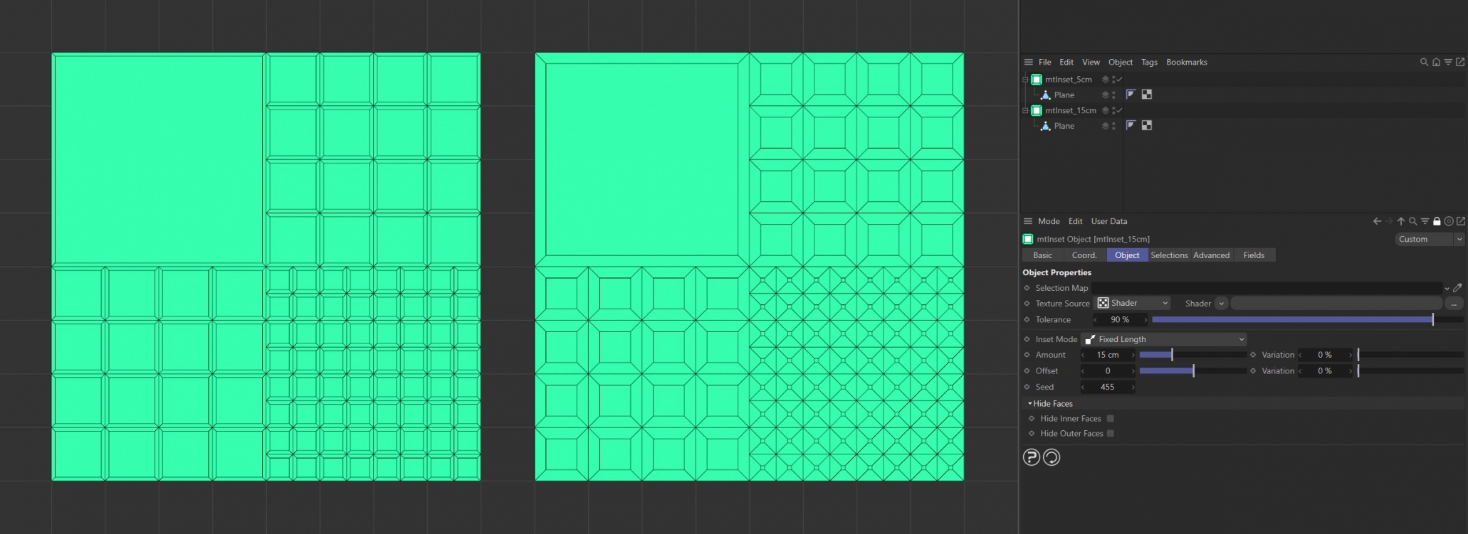
The Plane on the left has Inset Mode as Fixed Length with Amount set at 5cm. The Plane on the right is the same except the Amount value is increased to 15cm.
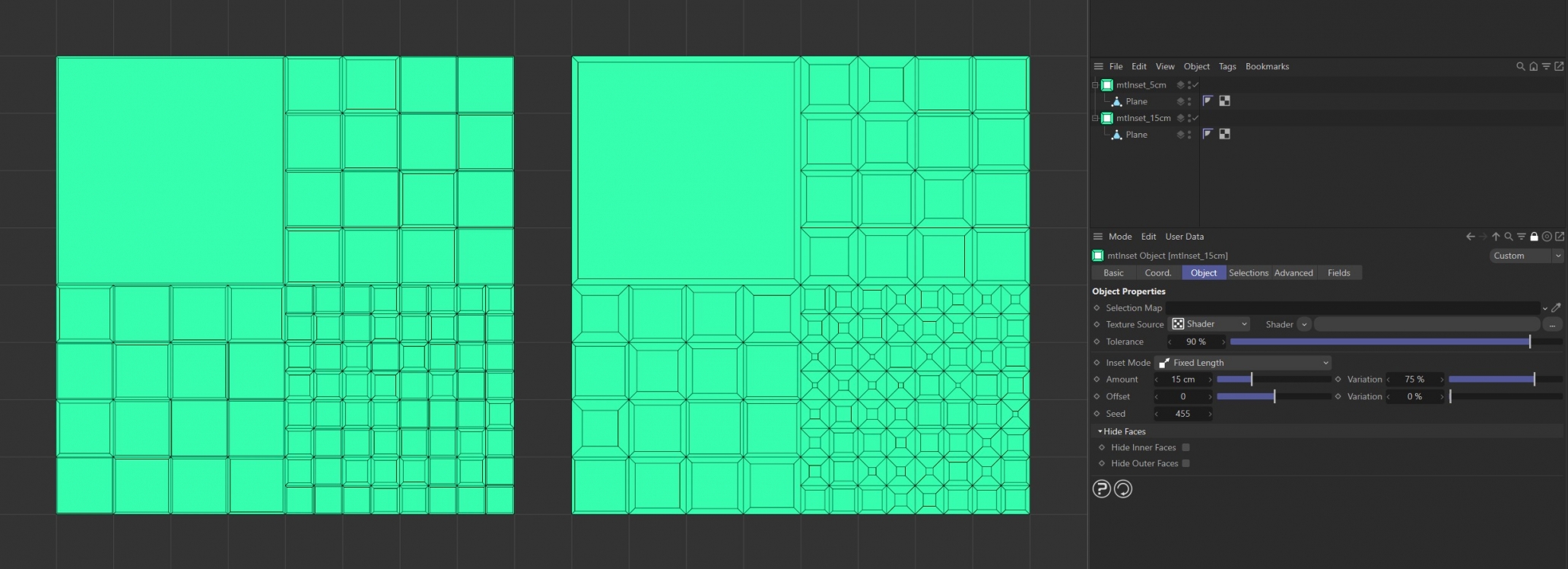
In this example, the two generators have different inset Amount settings, but both have a Variation setting of 75%.
Sampling Mode
There are two options: Per-Point and Centered.
Per-Point
This will sample the shader at the points of the polygons.
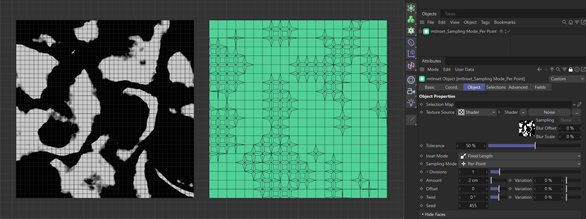
The Noise shader on the left is driving the extruding on the right-hand Plane, with a Per-Point setting sampling on the points of the polygons.
Centred
Use this mode to create evenly extruded inset polygons.
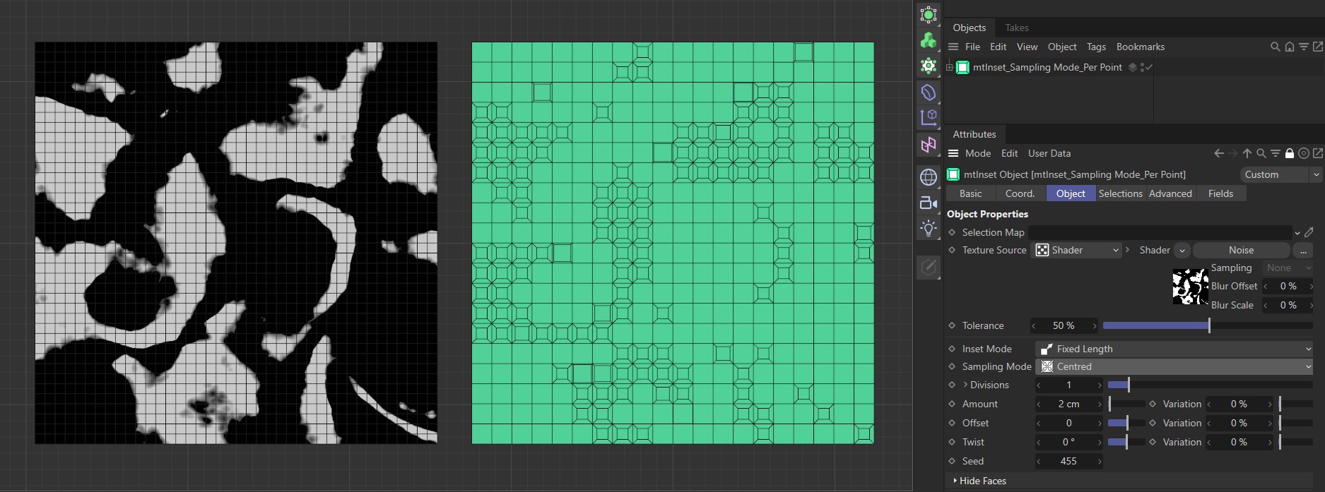
The Noise shader on the left is driving the extruding on the right-hand Plane, with a Centred setting sampling evenly across the polygons.
Divisions
Increasing this field divides the outer faces by generating more polygons.
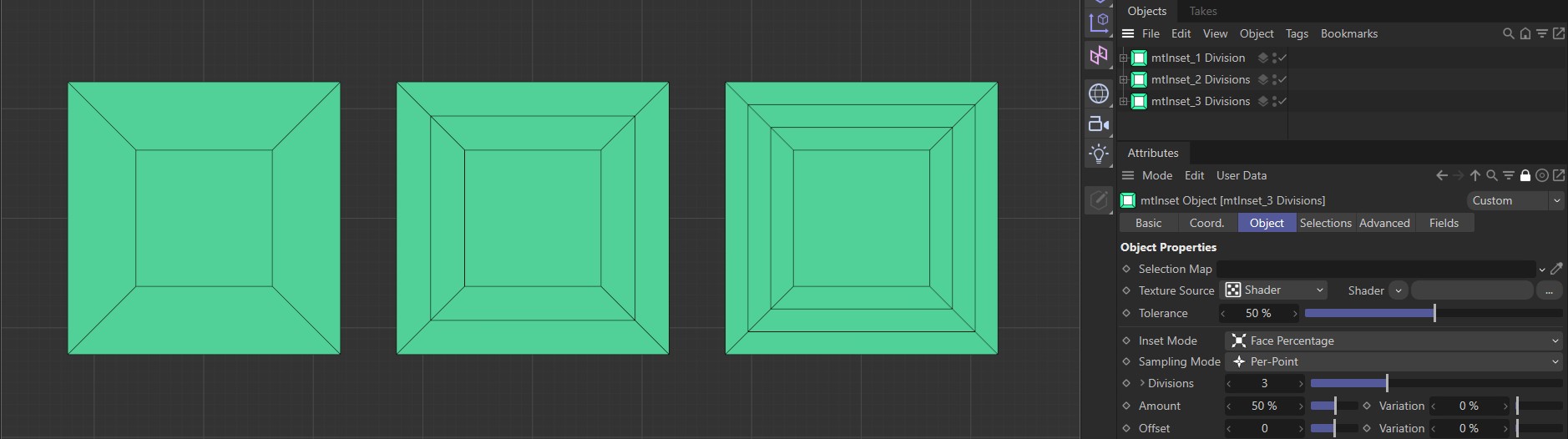
The polygons above have Divisions settings of 1, 2 and 3 respectively, from left to right.
Shape
Clicking on the arrow to the right of Divisions reveals a spline curve. Use this to adjust the profile shape of extruded insets.
Animation demonstrating manipulation of the spline curve to extrude insets.
Amount
In Face Percentage mode, use this field to set the appropriate inset size as a percentage.
In Fixed Length mode, use this field to set your required inset length.
Variation
You can add per-polygon variation using the Variation slider.
Animation to demonstrate the use of the Variation slider across the polygons.
Offset
You can extrude the inner face of the inset polygons. This slider controls the offset length.
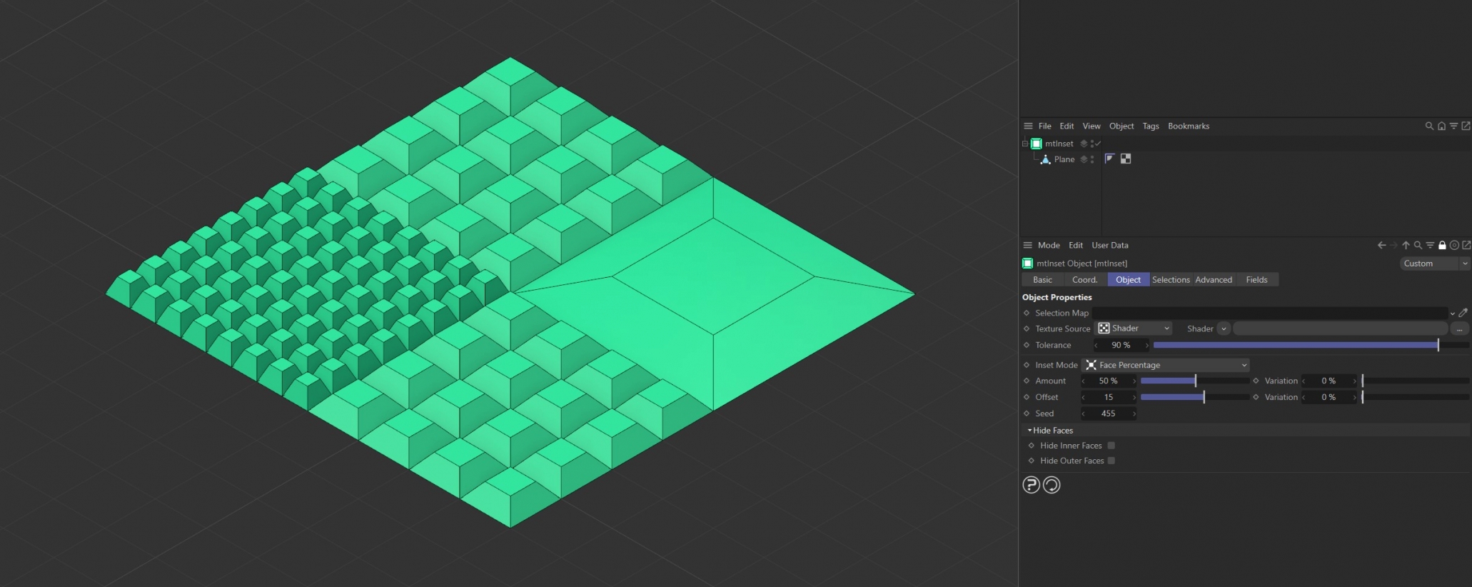
Offset is set at 15 on each of the inset polygons.
Variation
You can add offset variation using the Variation slider.
Animation demonstrating the use of the Variation slider, with an Offset setting of 50.
Twist
Increasing the value will allow you to twist the inset polygons by a set degree.
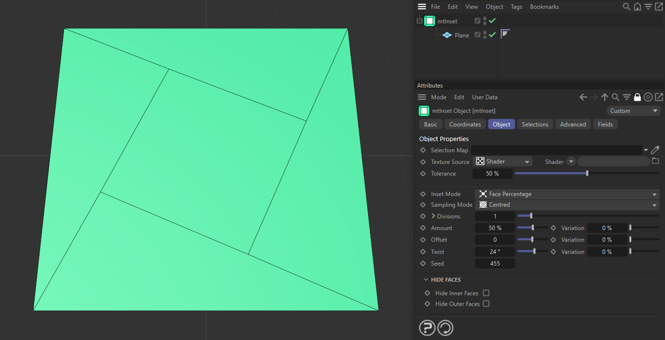
The inset is twisted at 24 degrees.
Variation
You can add twist variation, up to the Twist degree you have set, using the Variation slider.

Here, on a 4x4 grid, there is a Variation setting of 100%, making each inset a different degree of twisting.
Seed
Changing the Seed value will result in different variation configurations for both the Amount and Offset parameters.
Hide Faces
There is the option to change the scene geometry further by hiding faces, which you have created with mtInset, to give an interesting look.
Hide Inner Faces
Inner face polygons are hidden
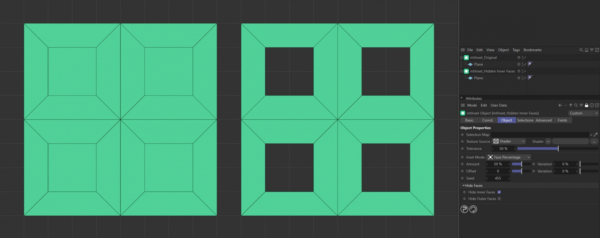
On the left is the result of the mtInset with no Hide Faces options enabled, therefore both inner and outer faces are being generated. The Plane on the right has Hide Inner Faces enabled.
Hide Outer Faces
Outer Face polygons are hidden
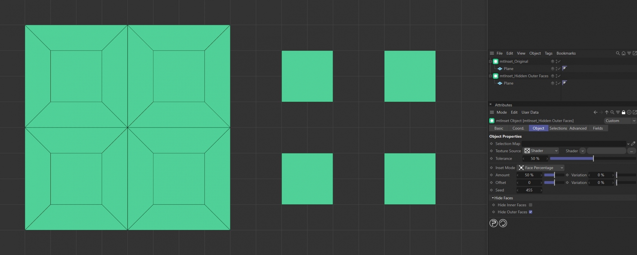
On the left is the result of the mtInset with no Hide Faces options enabled, therefore both inner and outer faces are being generated. The Plane on the right has Hide Outer Faces enabled.
Selections
You can create polygon selections based on the mtInset operation. Each selection is stored within a selection tag, which is automatically generated on activation.
Each selection can be visualized by activating Display Selection. You can change the color of the displayed selection using the color picker.
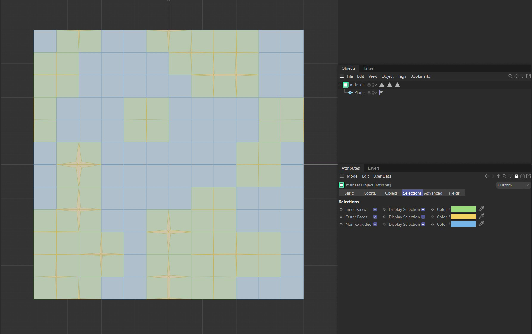
Plane insets visualized in the Selections tab color options.
Inner Faces
Create a polygon selection from the inset inner faces.
Outer Faces
Create a polygon selection from the inset outer faces.
Non-extruded
Create a selection from any remaining base-mesh polygons.
Advanced
Optimize
Newly generated topology can include duplicated points and surfaces. These can be eliminated by selecting Optimize.
Polygons
One or two point surfaces will be eliminated.
Unused Points
Any unused points will be deleted.
Points
Duplicated points will be eliminated.
Tolerance
Duplicated points are merged if they are within the Tolerance range set.
Fields
You can use the Fields options to control where mtInset operates.
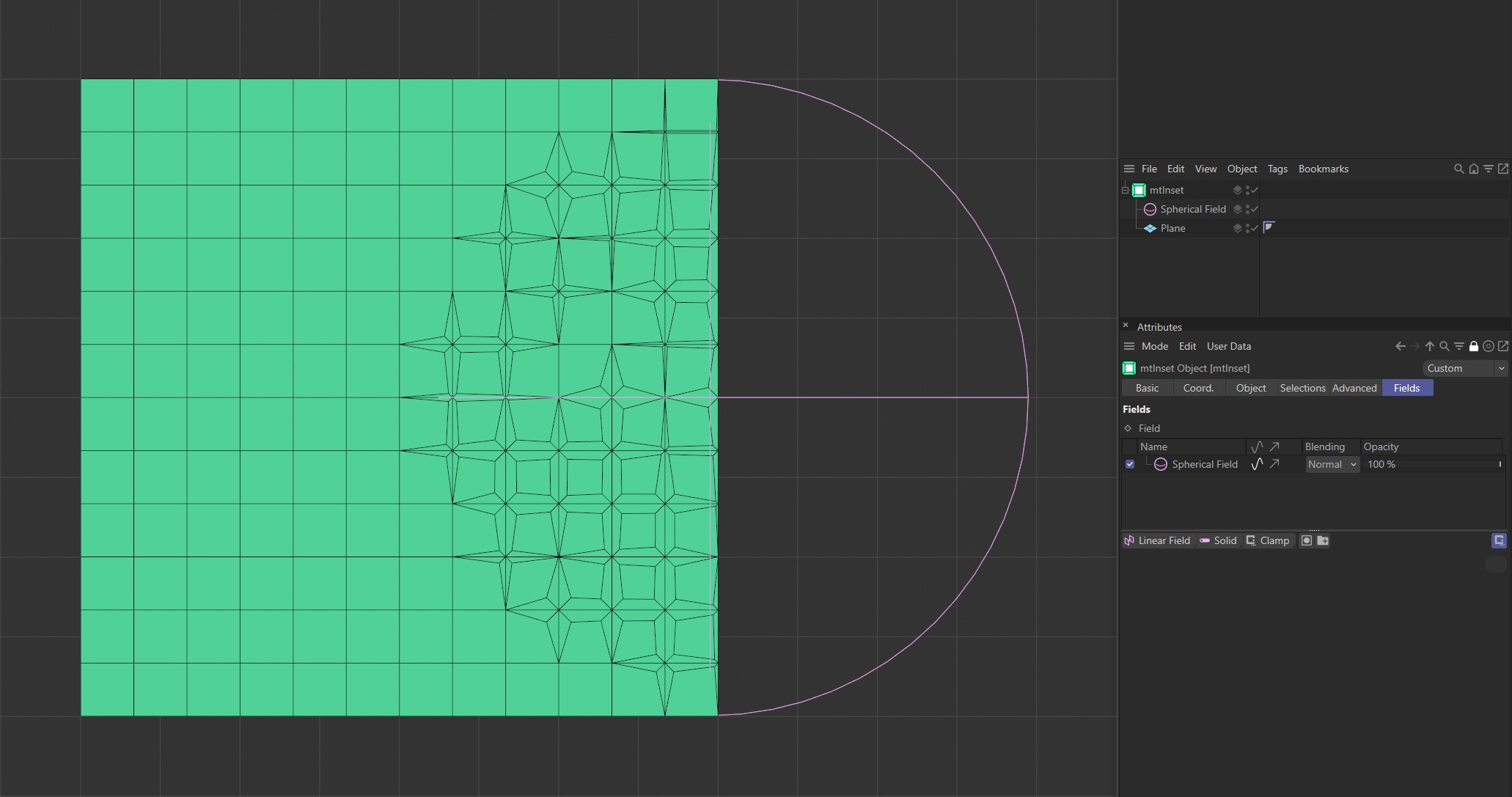
A Spherical Field driving inset generation on a Plane.