 mtDualGraph
 mtEdgeSpline
 mtInset
 mtPolyScale
 mtSelect
 mtShortestPath
 mtSplineSample
 mtSubDivider
 mtRemesh
 Global Settings
 Sphere
 Tree
Tree Koch
Koch Dragon
 Fern
Fern Fibonacci
 mtShellGen
mtShellGen extrudes polygon faces and creates hull and cap geometry. This can be used to create 3D shells from polygon faces.
Overview Video
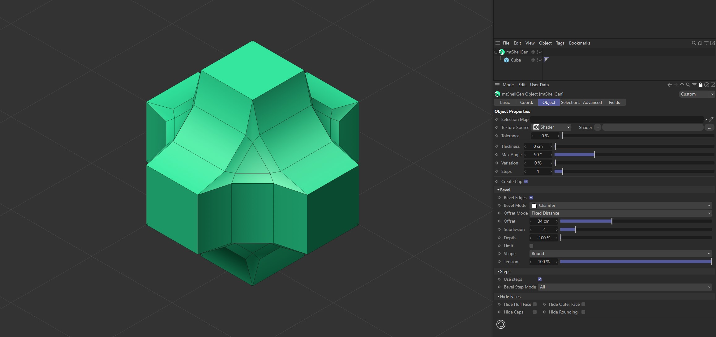
mtShellGen using bevel options on a source Cube to create this geometry.
Object
Object Properties
Selection Map
You can use vertex map or selection tags to define which polygons are extruded. Drag the tag from the Object Manager into the Selection Map link field.
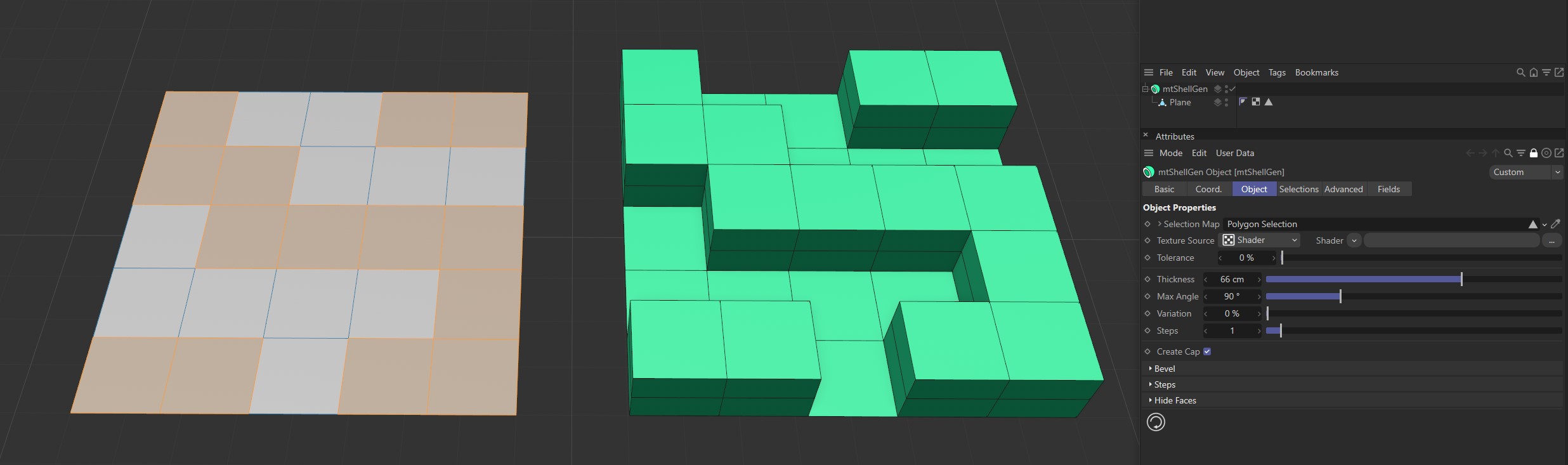
The Plane on the left has a polygon selection tag, which is displayed in the viewport. An identical Plane is on the right, as a child of a mtShellGen. The selection tag is driving the polygon extrusion.
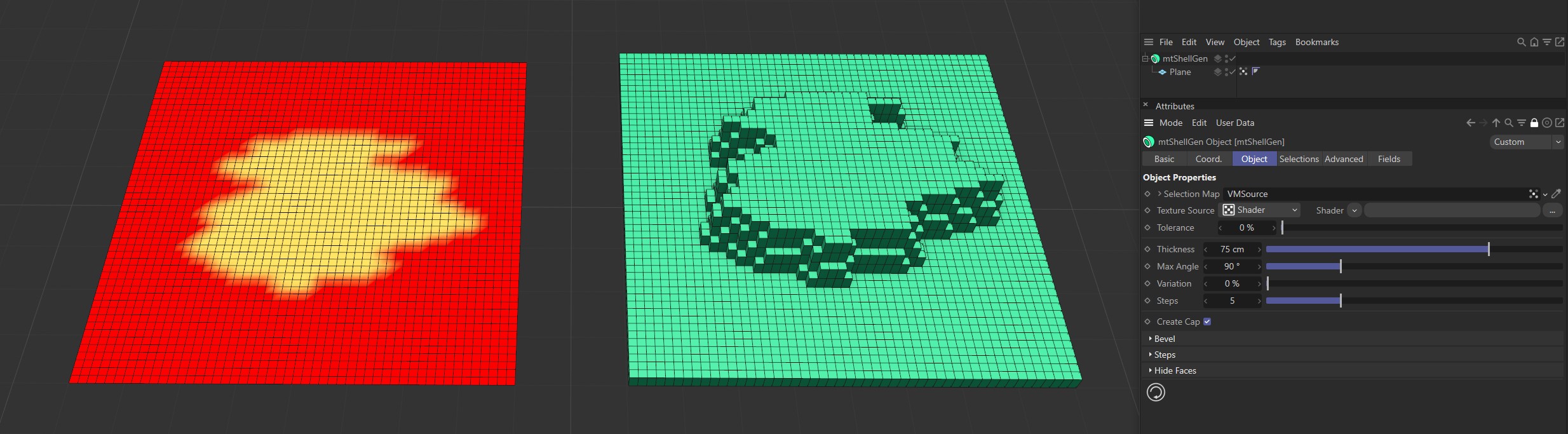
The Plane on the left has a vertex map, which is displayed in the viewport. An identical Plane is on the right, as a child of a mtShellGen. The vertex map is driving the extrusion.
Texture Source
You can use shaders and images to control which polygons are extruded. There are two options: Shader and Texture Tag. Both use color value to define which polygons are extruded.
Texture Tag
This mode requires a Cinema4D material. Place the material on the mtSelect and you will see a texture tag appear alongside it in the Object Manager. Drag this texture tag into the Texture Tag link field.
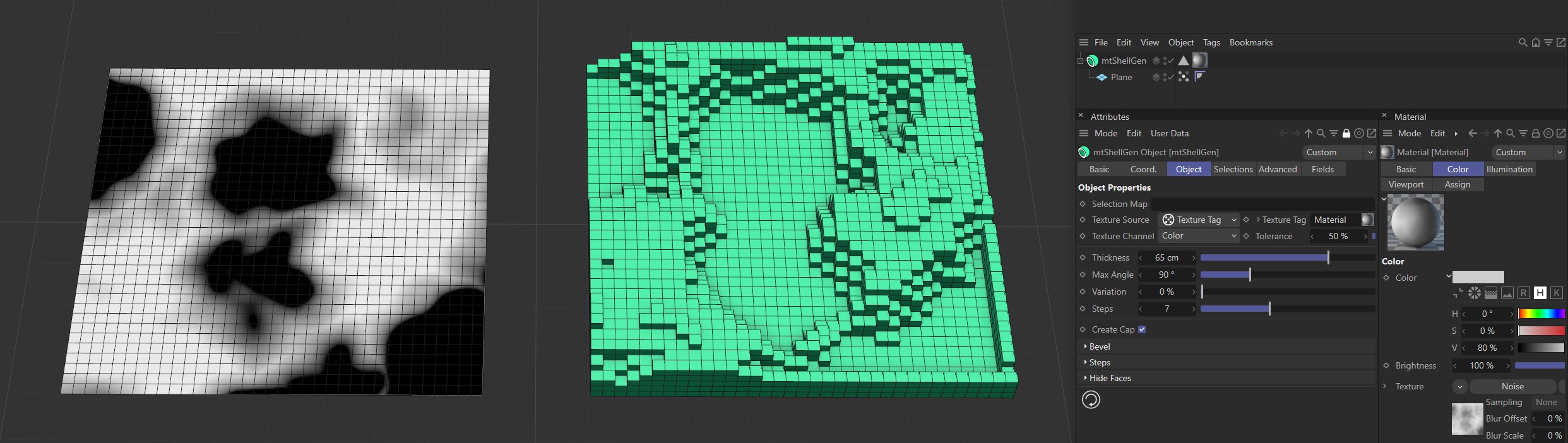
Texture Source set to Texture Tag, with the Noise material on the left driving the extrusion on the right-hand Plane.
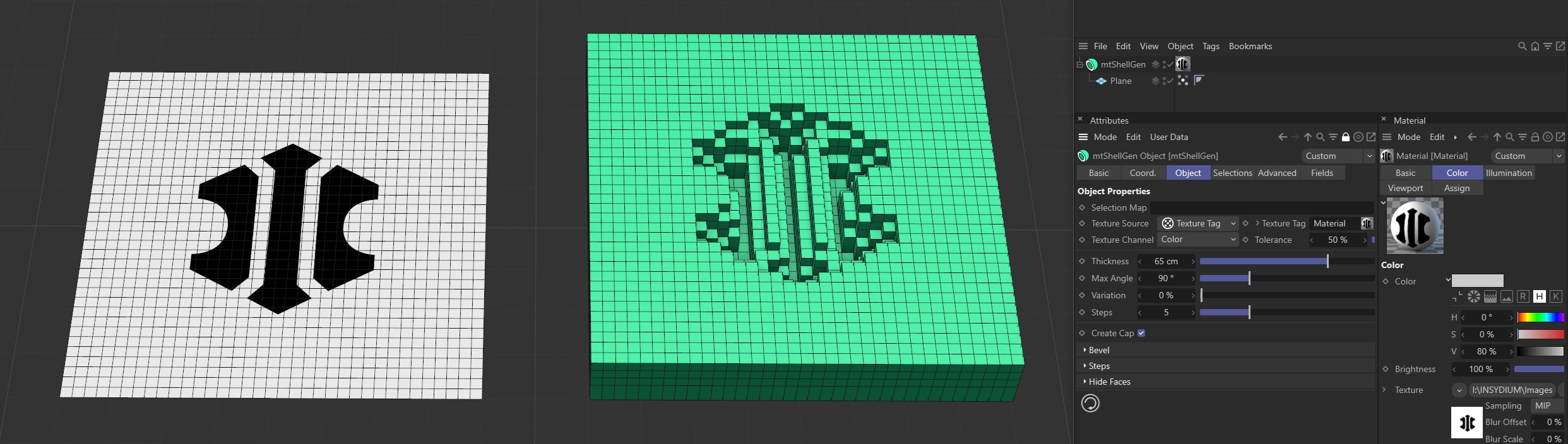
Texture Source set to Texture Tag, with the bitmap material on the left driving the extrusion on the right-hand Plane.
Texture Channel
Use the Texture Channel pull-down to select which material channel you wish to reference. This is set to Color by default.
Shader
Use the Shader drop-down to select an image, sequence or shader.
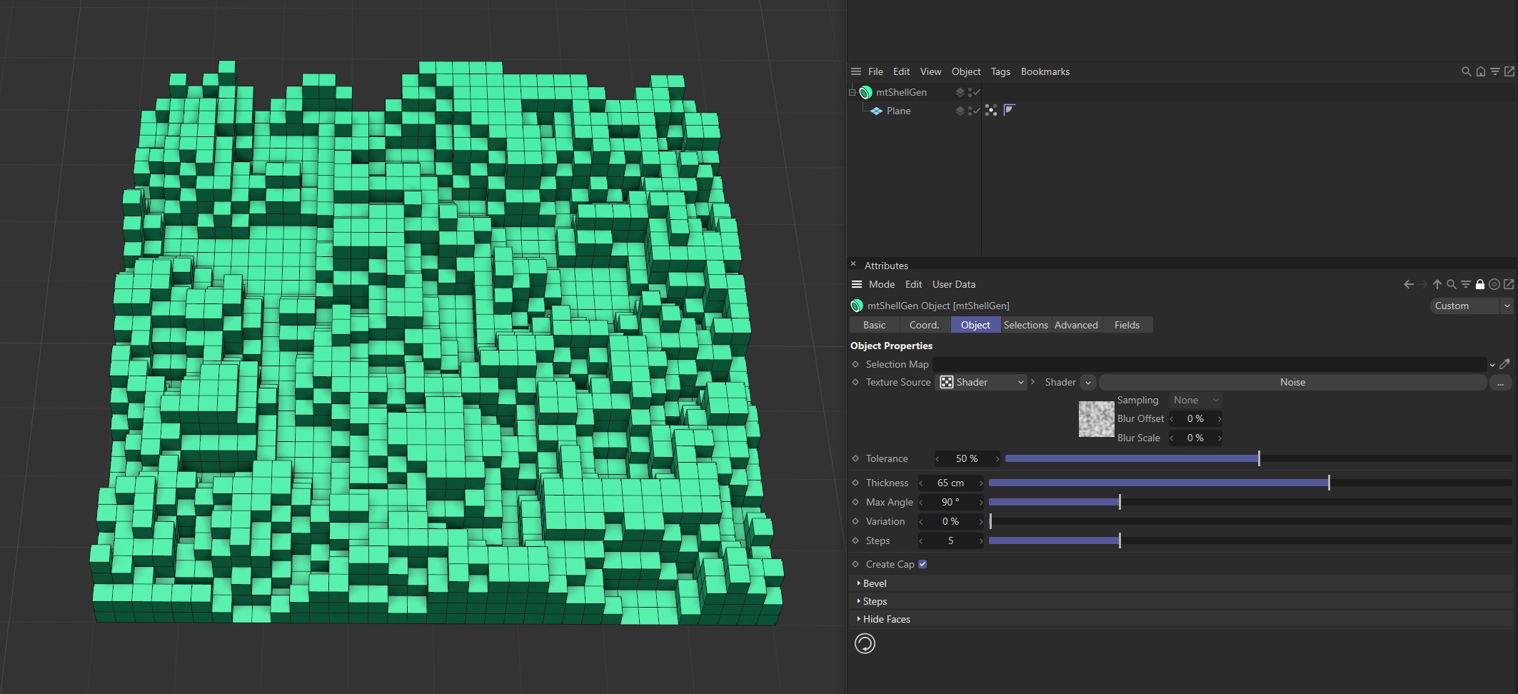
Noise shader driving the extrusion on the Plane.
Tolerance
Use the Tolerance slider to adjust the point at which polygons are extruded.
Lower tolerance values will allow polygons to be extruded in darker areas.
Higher tolerance values will allow polygons to be extruded in lighter areas.
Demonstration of the effects of the Tolerance slider with a Noise shader.
Thickness
This setting defines the amount of extrusion.
Animation sequence demonstrating the effects of the Thickness slider.
Max Angle
If the angle at which polygons meet is less than the defined Max Angle, they will be separated on extrusion.
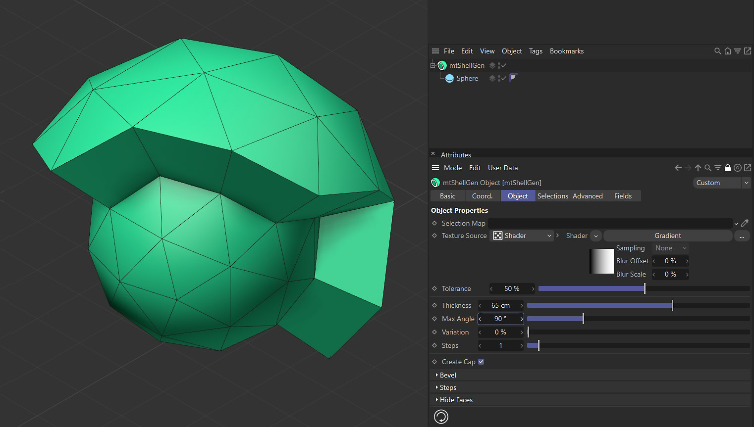
Max Angle set at 90 degrees.
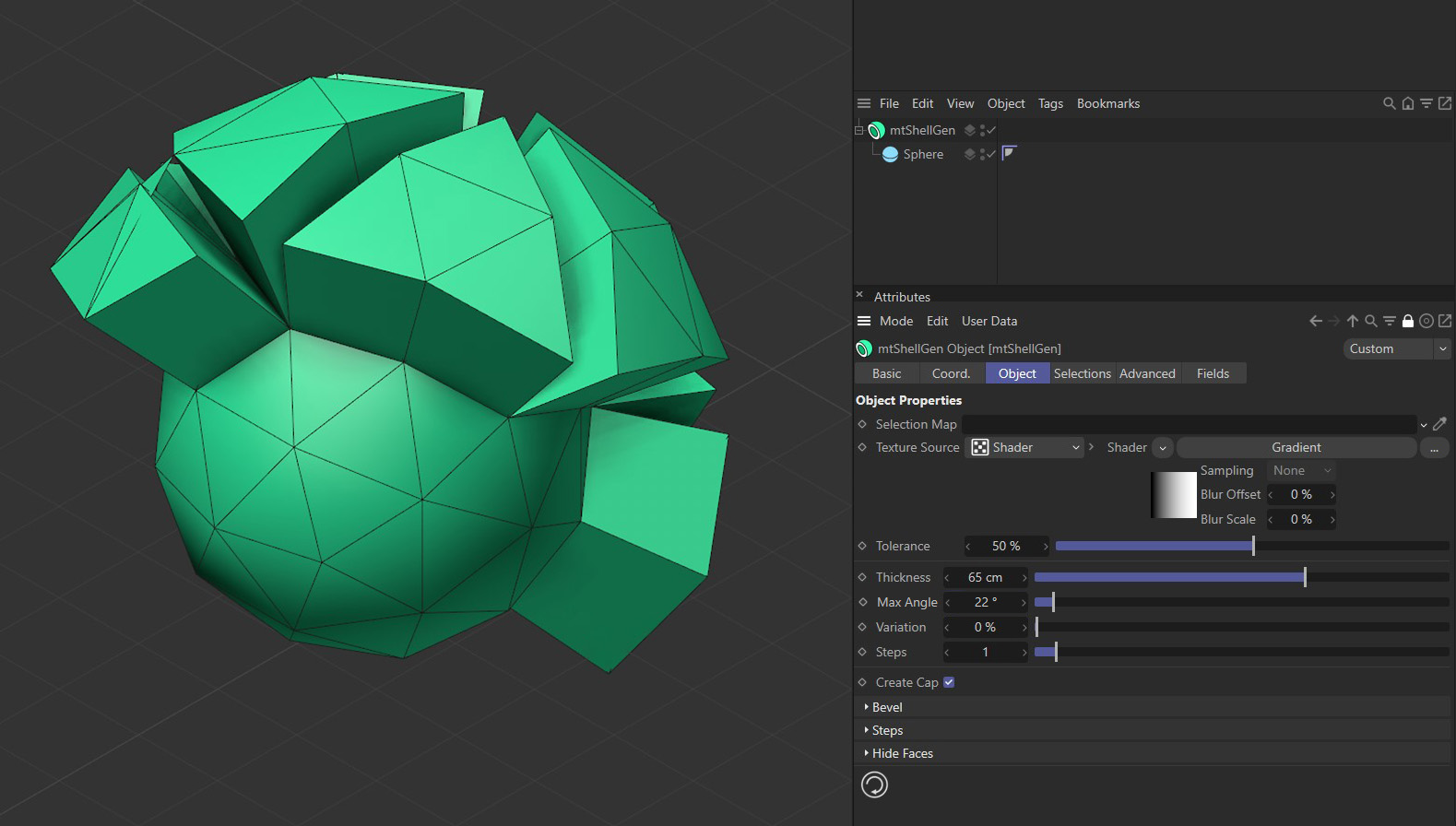
Max Angle set at 22 degrees.
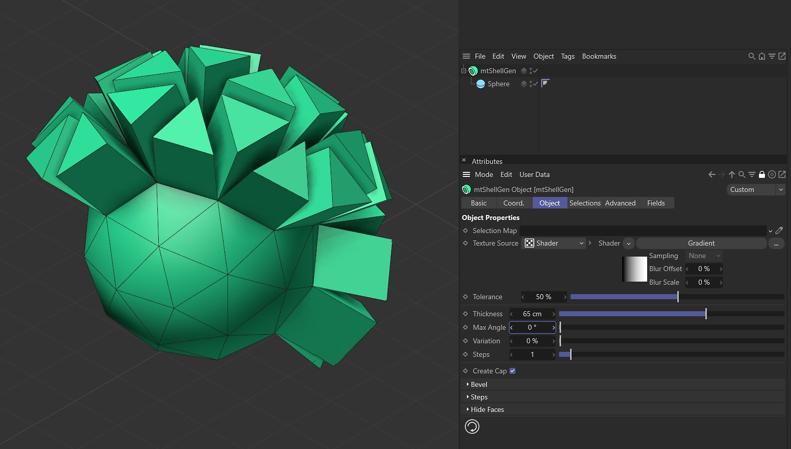
Max Angle at set at (zero) 0 degrees.
Variation
Use this slider to add per-face variation to the Thickness amount.
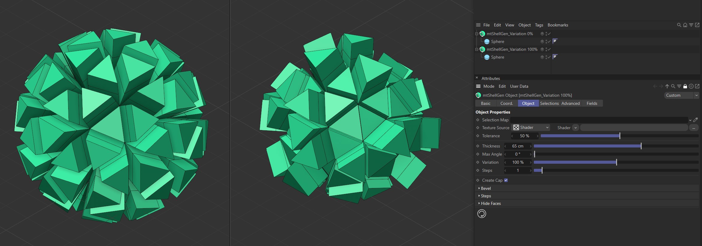
The mtShellGen on the left has a Variation value of 0 (zero) %. The mtShellGen on the right has a Variation value of 100%.
Steps
When polygons are extruded they create new hull geometry. You can add segments to the hull geometry by increasing the Steps value.
Animation sequence demonstrating the effect of the Steps slider, adding steps to the polygon geometry.
Bevel
You can add bevels to the edges of your geometry.
Bevel Edges
Select to activate beveling and options.
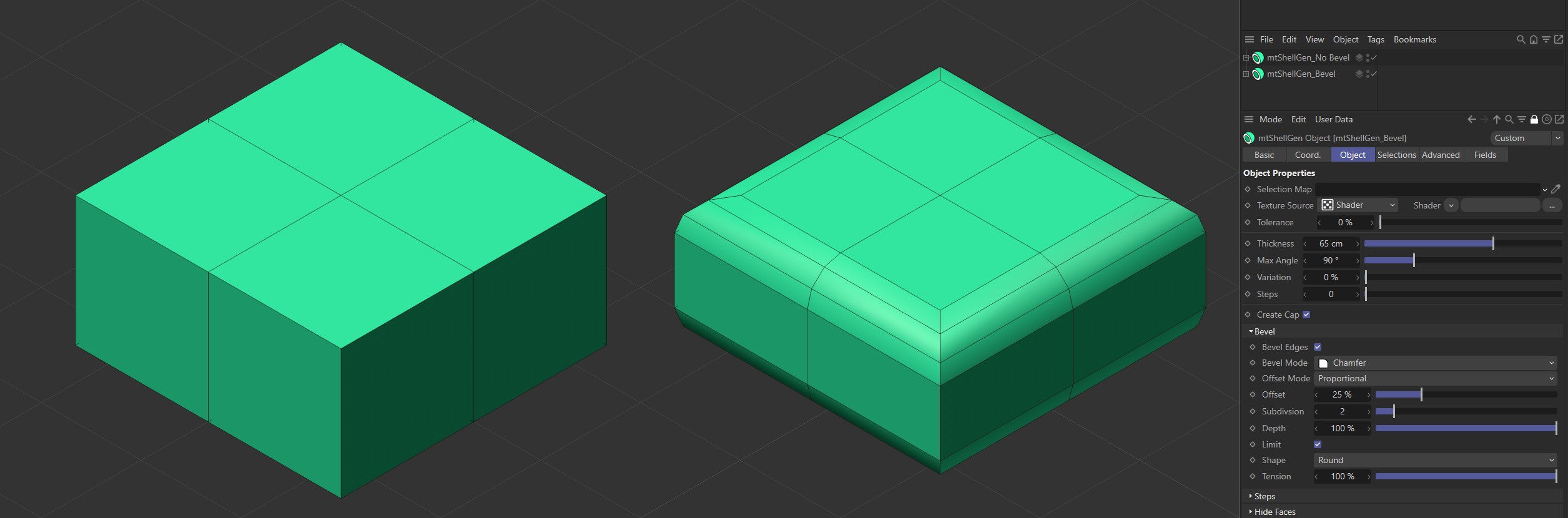
The Bevel Edges option in the left mtShellGen is disabled. It is enabled on the right, resulting in beveled edges.
Bevel Mode
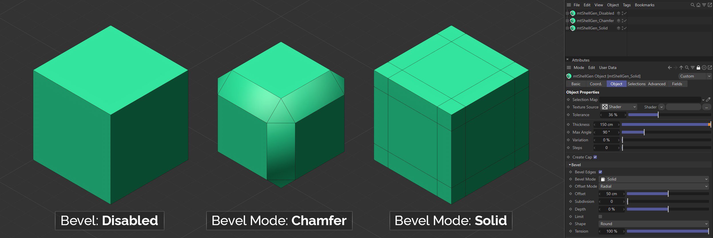
There are two Bevel Mode settings to choose from: Chamfer and Solid.
Chamfer
This mode will change the shape of your geometry by creating curved edges and corners.
Solid
This mode will leave the shape of your geometry unchanged, but will generate parallel edges along neighboring polygons. This can be used to maintain edges when using sub-division surfaces.
Offset Mode
There are three different bevel Offset Mode settings: Proportional, Fixed Distance and Radial.
All Offset Mode settings generate at least two new outer edges, that run parallel to the original edge. A new surface is created between these lines.
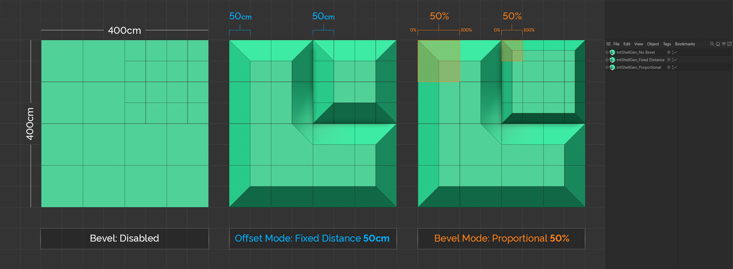
All three Planes are identical. Note the varying polygon size. The middle Plane is set to the Offset Mode of Fixed Distance, with an Offset of 50cm. In this mode, every bevel has the same length, irrespective of its base polygon size. The Plane on the right is set to the Offset Mode of Proportional, with an Offset of 50%. In this mode the bevels are proportional in size to their base polygons.
Proportional
In this mode, the distance between the new edges and the original edge is defined as a percentage. You set this percentage amount using the Offset slider.
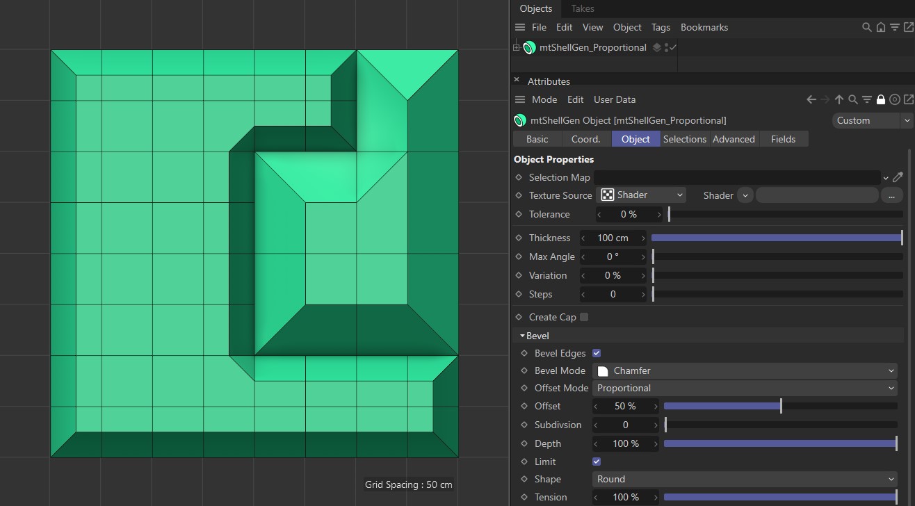
Offset Mode set as Proportional, with a 50% offset setting.
Fixed Distance
In this mode, the distance between the new edges and the original edge is set by a fixed value. You set this amount using the Offset slider.
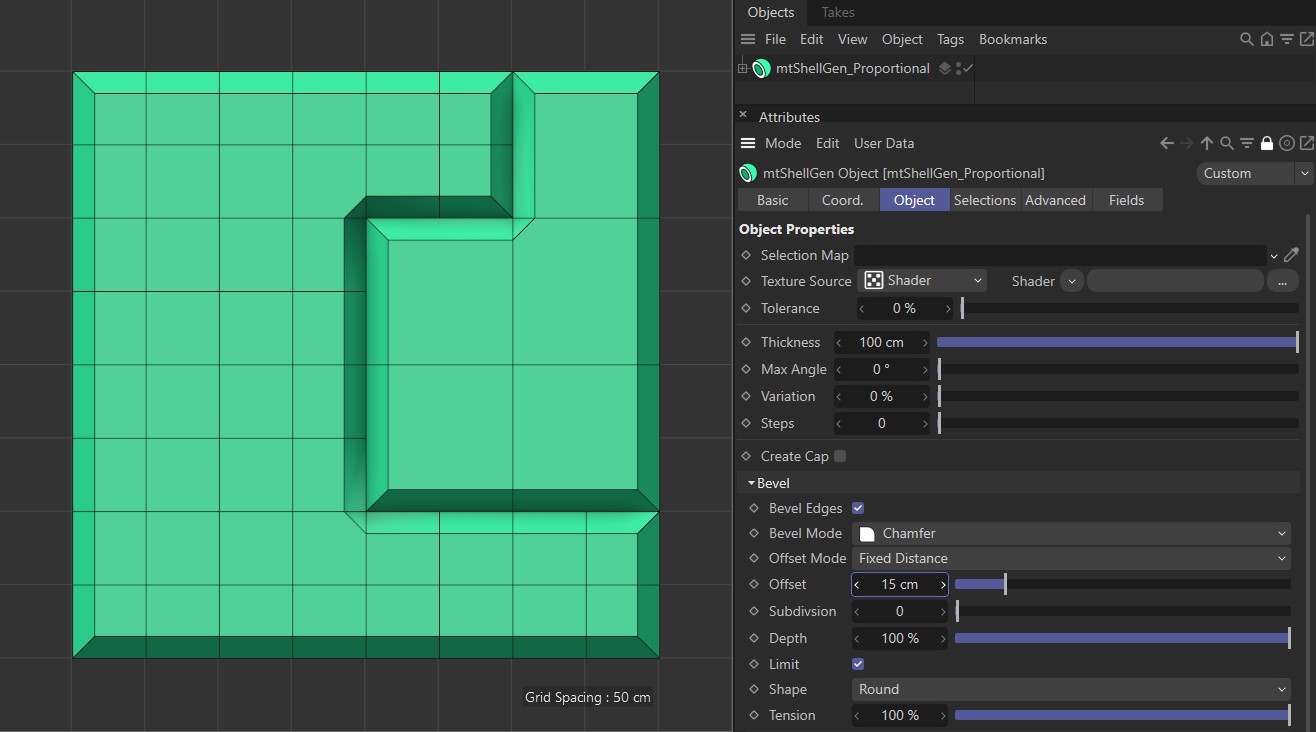
Offset Mode set as Fixed Distance, with an Offset of 15cm.
Radial
This mode works in the same way as the Fixed Distance mode. However, in objects where three edges meet, the corner bevel will be more spherical in shape.
Offset
You can adjust the size of the bevel using the Offset slider.
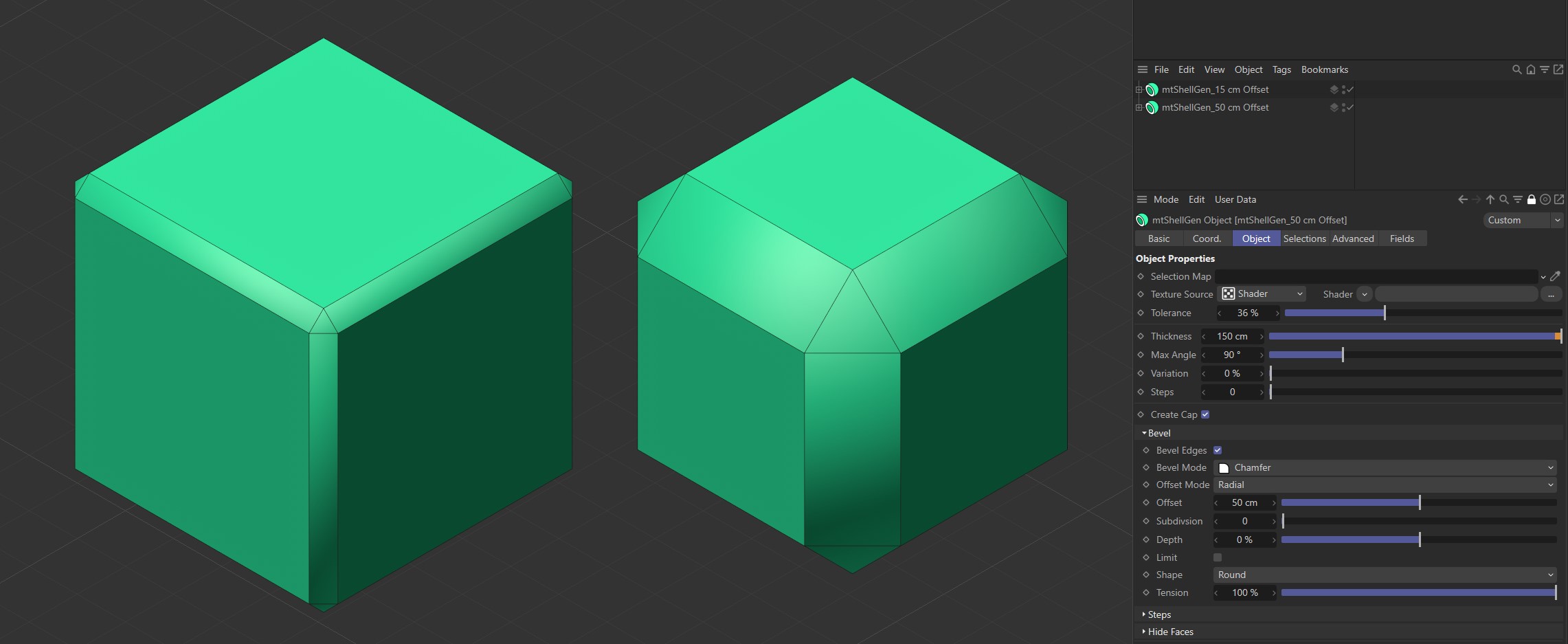
The left-hand Cube has an Offset of 15 cm. The Offset is 50 cm for the Cube on the right.
Subdivision
Use this Subdivision slider to add more geometry to your bevel faces. This will create smoother curves.
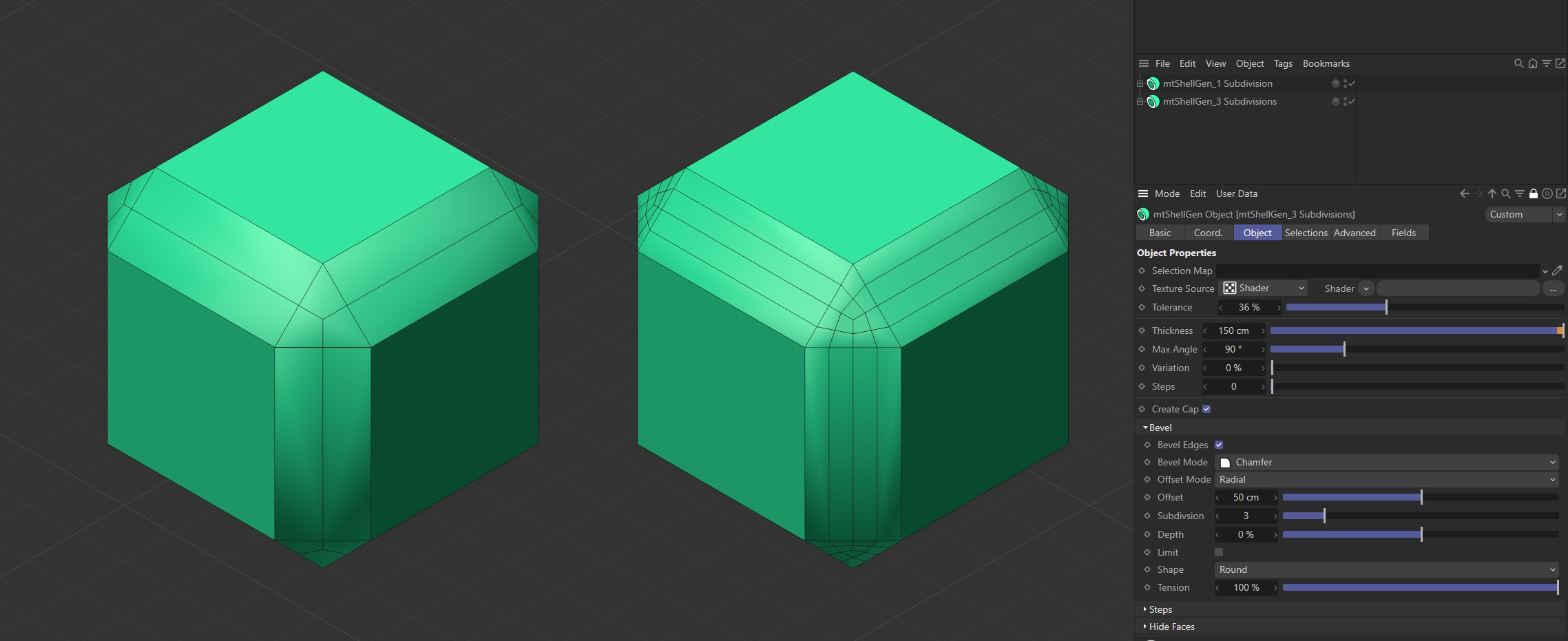
The first Cube has Subdivision set to one and the second Cube is set to three.
Depth
The Depth percentage setting will add curve to your bevel profile. 100% will create a convex bevel and -100% will create a concave bevel.
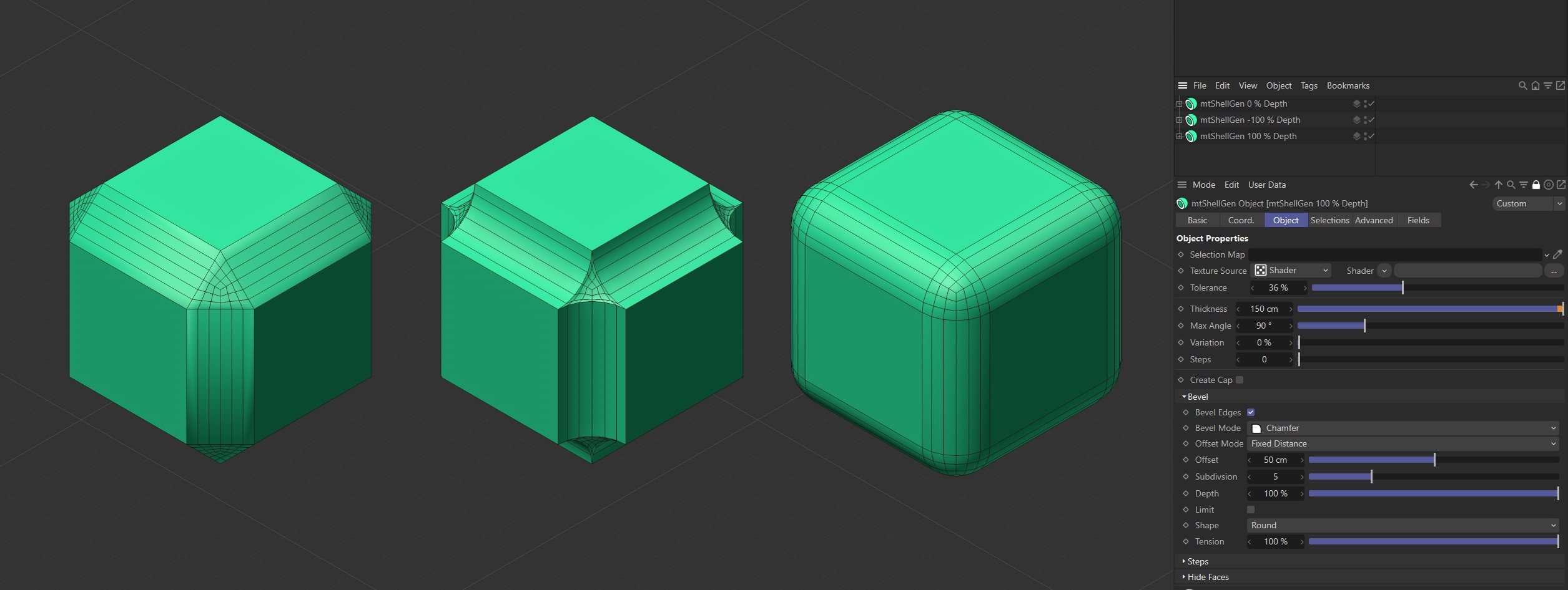
The first Cube is set with a Depth value of 0 (zero) %, the second is set to -100% and the third Cube has Depth set to 100%.
Limit
In Fixed Distance and Radial modes it is possible for the new Bevel Edges to be offset beyond the next edge of the original mesh. You can prevent this by activating the Limit setting.
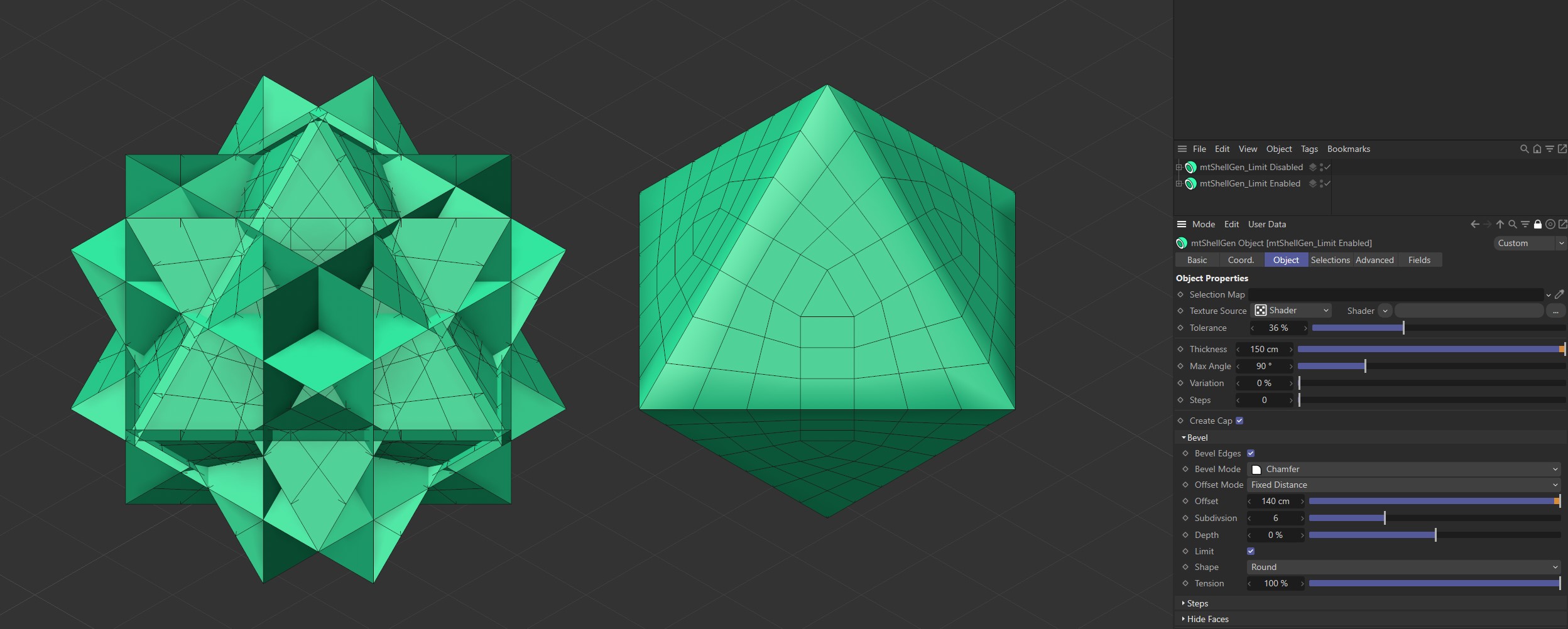
Limit is disabled on the first Cube and enabled on the second.
Shape
You can shape your bevel using three modes: Round, User and Profile.
Round
This is the default mode and will create a rounded bevel shape. The level of rounding is driven by the Depth value.
Shape set to Round.
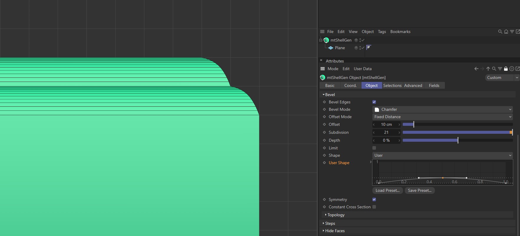
User
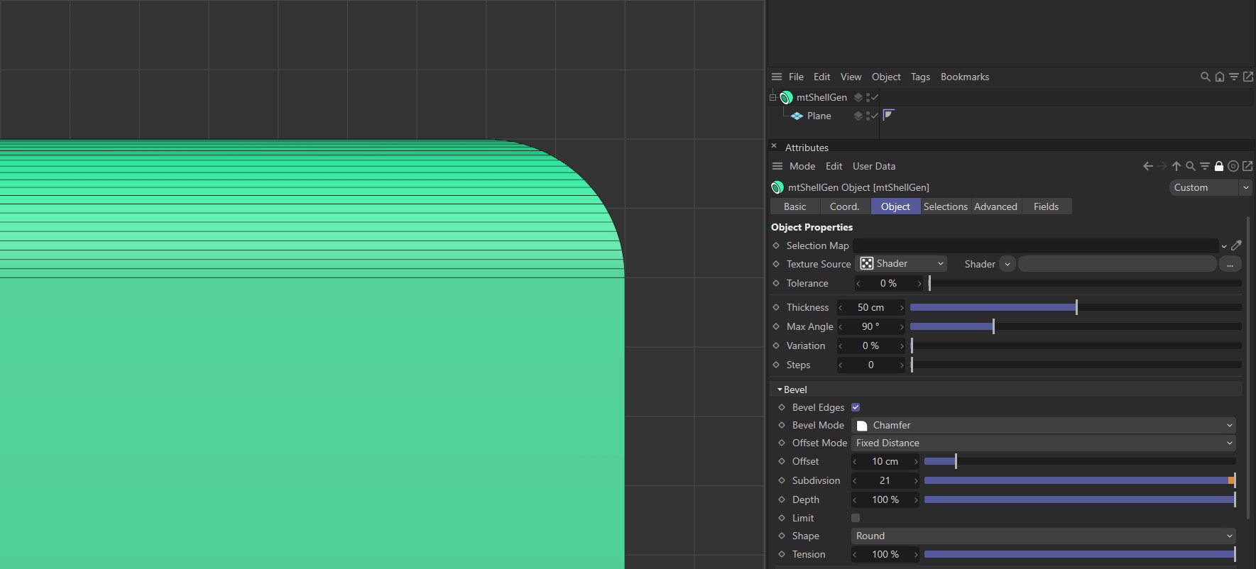
This mode activates a spline curve, which can be adjusted to shape the new edge.

Shape set to User with a flat, linear curve.
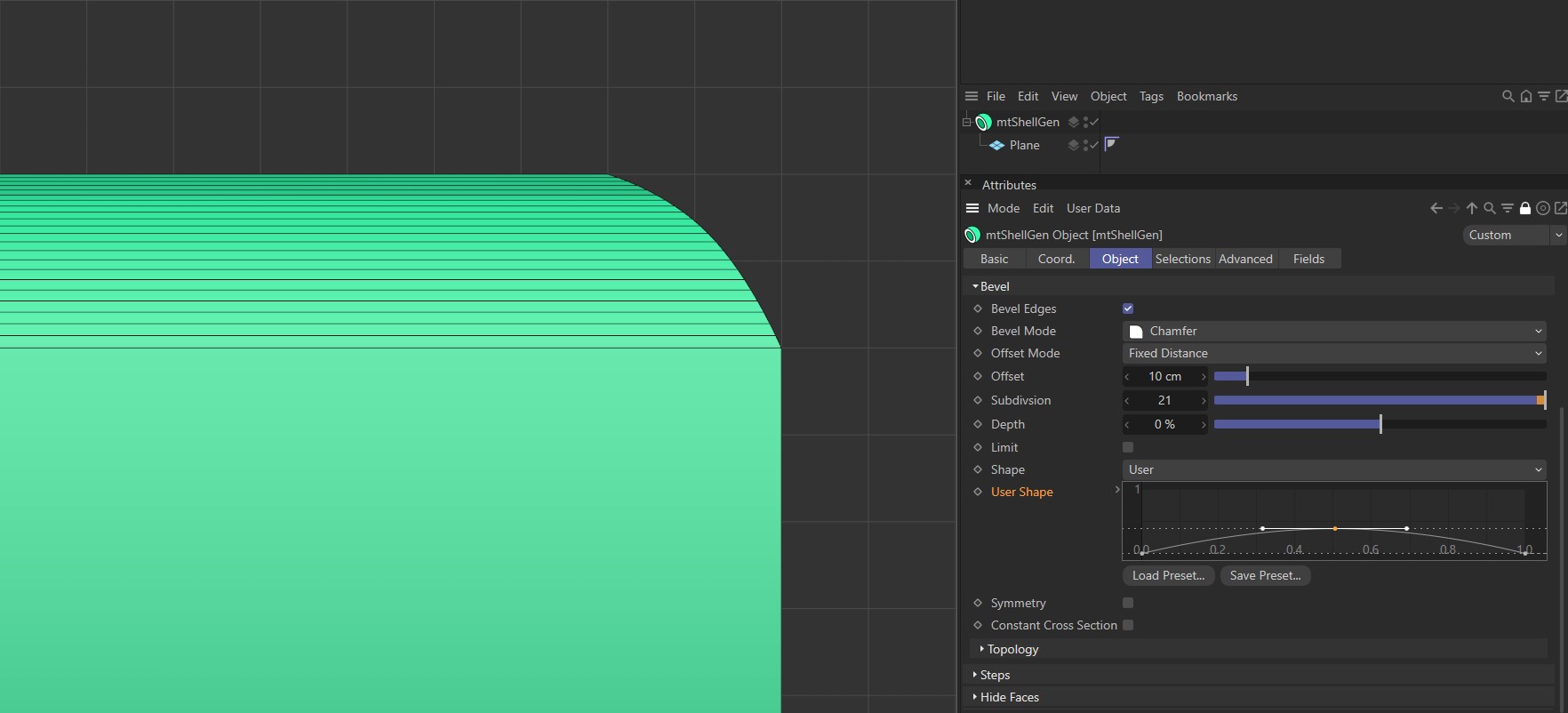
Shape set to User with a smooth curve. Note the curved bevel profile.
Symmetry
If activated, the spline graph will be mirrored.

With Symmetry disabled and Shape set to User, the curve is mapped to the start and end point of the bevel.
With Symmetry enabled and Shape set to User, the curve is mirrored at the centre point of the bevel.
Constant Cross Section
In more complex meshes, this setting can generate a more consistent bevel.
Profile
In this mode, you can design the shape of your bevel using a spline. The Subdivision settings of the bevel will be defined by the spline's intermediate points.
Profile Spline
Drag your desired profile spline into this link field.
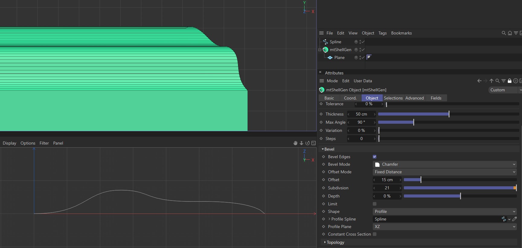
Profile Spline driving the bevel shape, above.
Profile Plane
You can set the Profile Plane to XY, XZ or YZ. Your choice will depend on the plane in which your spline is orientated.
Constant Cross Section
In more complex meshes, this setting can generate a more consistent bevel.
Tension
This setting is active when Shape mode is set to Round. At 100% the bevel will create a circular profile. Reducing the Tension value will create an elliptical profile.
Video sequence showing the bevel becoming more circular as the Tension setting percentage increases.
Steps
You can choose to define whether a Texture Source affects either the extrude Thickness setting only, or the extrude Thickness setting and the value for the number of hull Steps.
Use Steps
Activate this setting for a Texture Source to affect both the Thickness and Step amounts.
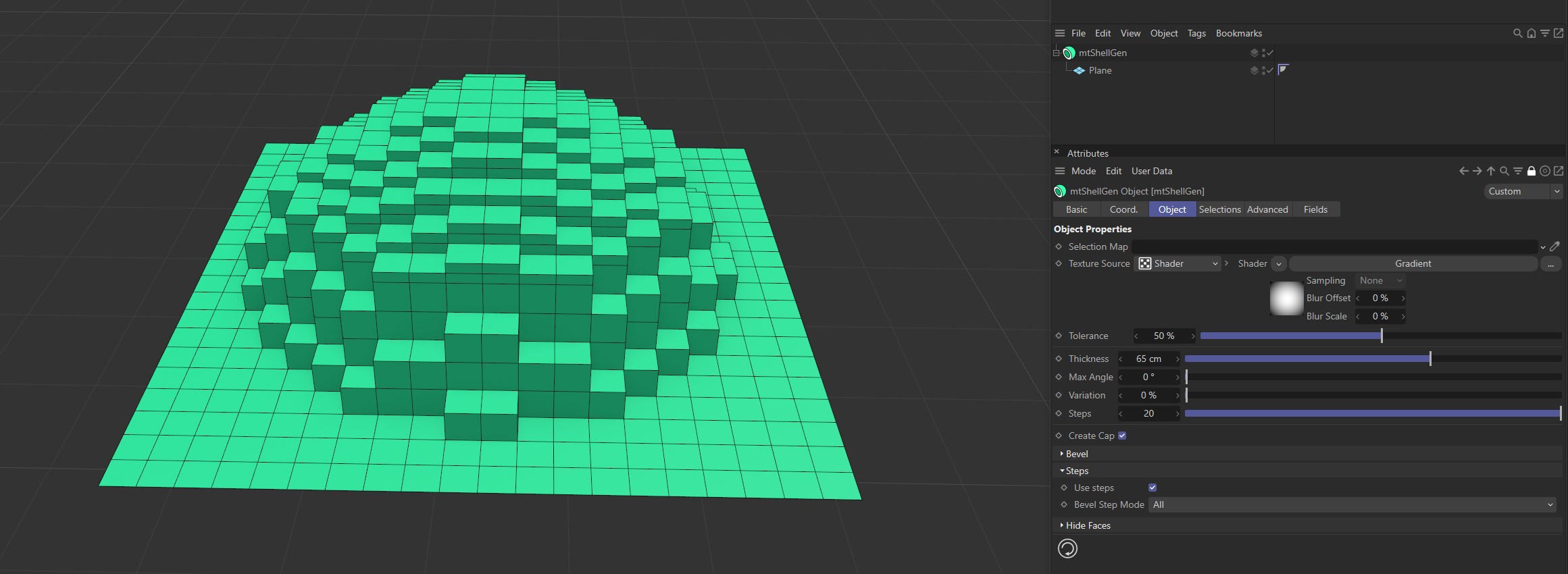
Use Steps enabled.
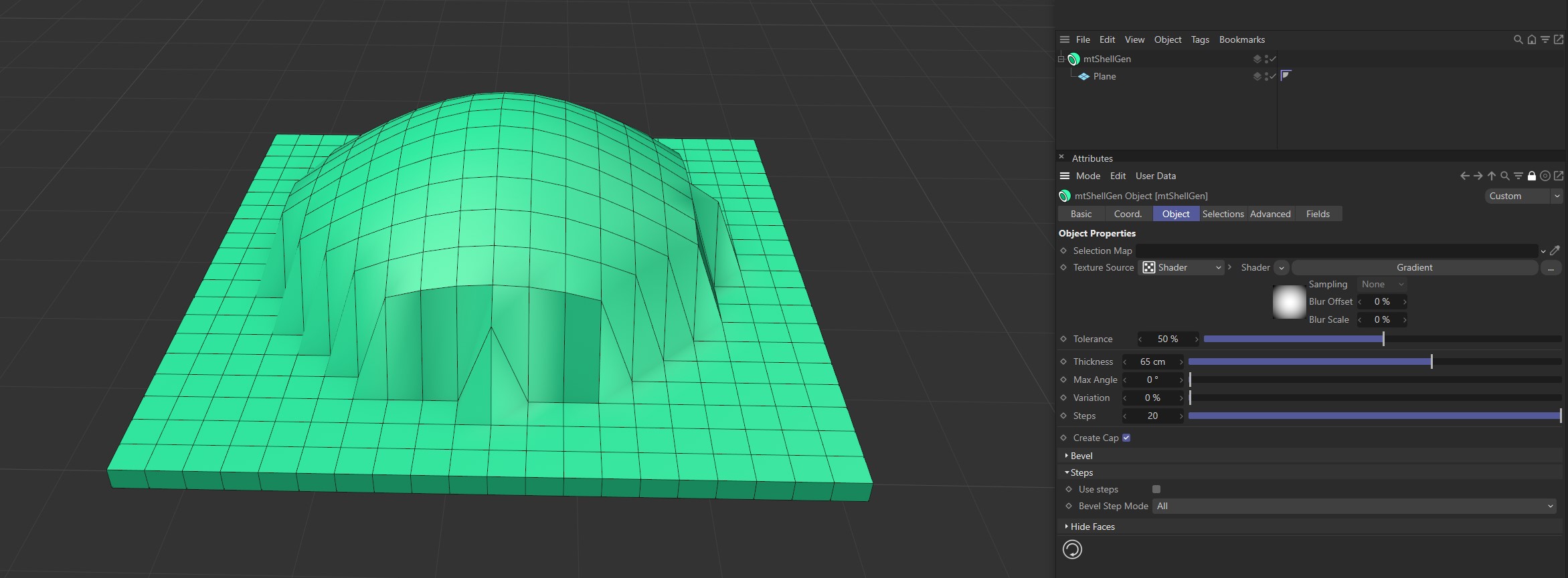
Use Steps disabled.
Bevel Step Mode
With Use Steps active, you have two Bevel Step Mode options: All and Caps.
All
Select All to bevel every step edge.
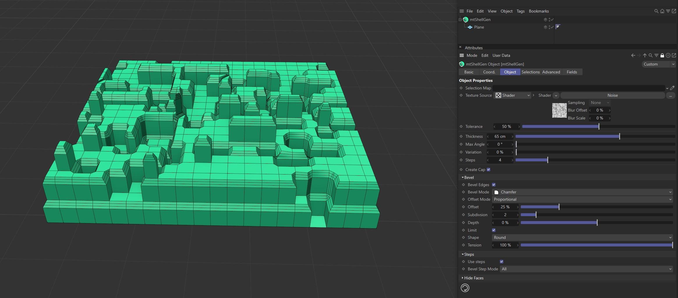
Bevel Step Mode set to All.
Caps
Select Caps to only bevel the outer face edge.
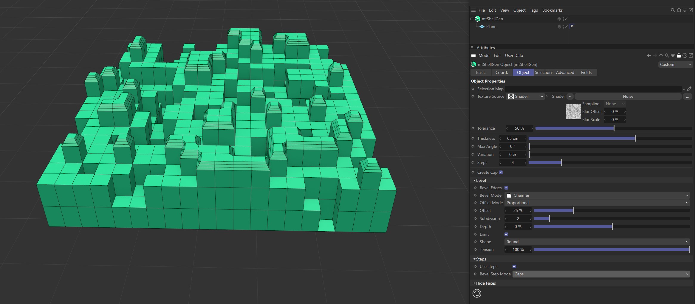
Bevel Step Mode set to Caps.
Hide Faces
Hide Hull Face
Hull faces are hidden.
Hide Outer Face
Outer faces are hidden.
Hide Caps
Caps are hidden.
Hide Rounding
Rounding polygons are hidden.
Video sequence demonstrating the Hide Faces options.
Selections
You can create various polygon selections based on the mtShellGen operation. Each selection is stored within a selection tag, which is automatically generated on activation. Each selection can be visualized by activating Display Selection. You can change the color of the displayed selection using the color picker
Video sequence demonstrating the Selections options.
Hull Face
Create a polygon selection from the newly-generated hull faces.
Outer Face
Create a polygon selection from the outer faces.
Caps
Create a polygon selection from the caps.
Rounding
Create a polygon selection from the rounding created by the bevel.
Advanced
Optimize
Newly generated topology can include duplicated points and surfaces. These can be eliminated by selecting Optimize.
Polygons
One or two point surfaces will be eliminated.
Unused Points
Any unused points will be deleted.
Points
Duplicated points will be eliminated.
Tolerance
Duplicated points are merged if they are within the Tolerance range setting.
Fields
You can use the Fields options to control where mtShellGen operates.
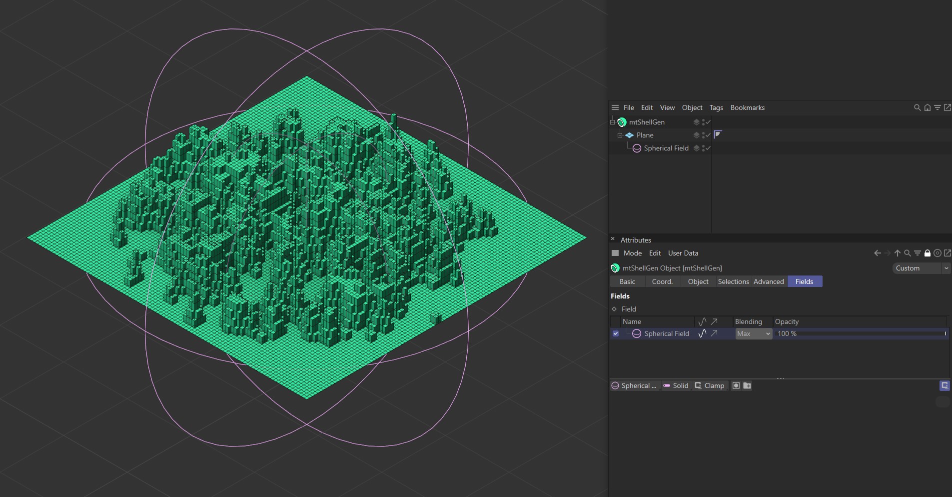
A Spherical Field being used to control extrusion on a Plane.