 mtDualGraph
 mtEdgeSpline
 mtInset
 mtPolyScale
 mtSelect
 mtShellGen
 mtShortestPath
 mtSplineSample
 mtSubDivider
 Global Settings
 Sphere
 Tree
Tree Koch
Koch Dragon
 Fern
Fern Fibonacci
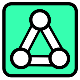 mtRemesh
mtRemesh generates a Delauney Triangle-based mesh for the input geometry. You can create controllable, uniform or adaptive triangulation over the mesh for simulation and rendering tasks.
Overview Video
Scene object on the left and - on the right - as a child of mtRemesh, reflecting the settings in the Attributes Manager.
Object
Object Properties
Selection Map
You can use a vertex map or selection tags to control where, on your object, remeshing occurs.
Drag the tag from the Object Manager into the Selection Map link field.
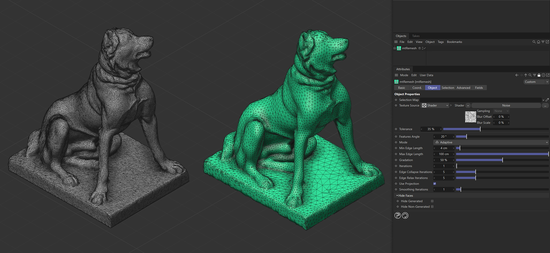
The Plane on the left has a polygon selection tag, which is displayed in the viewport. An identical Plane is on the right, as a child of mtRemesh, driving where remeshing takes place.
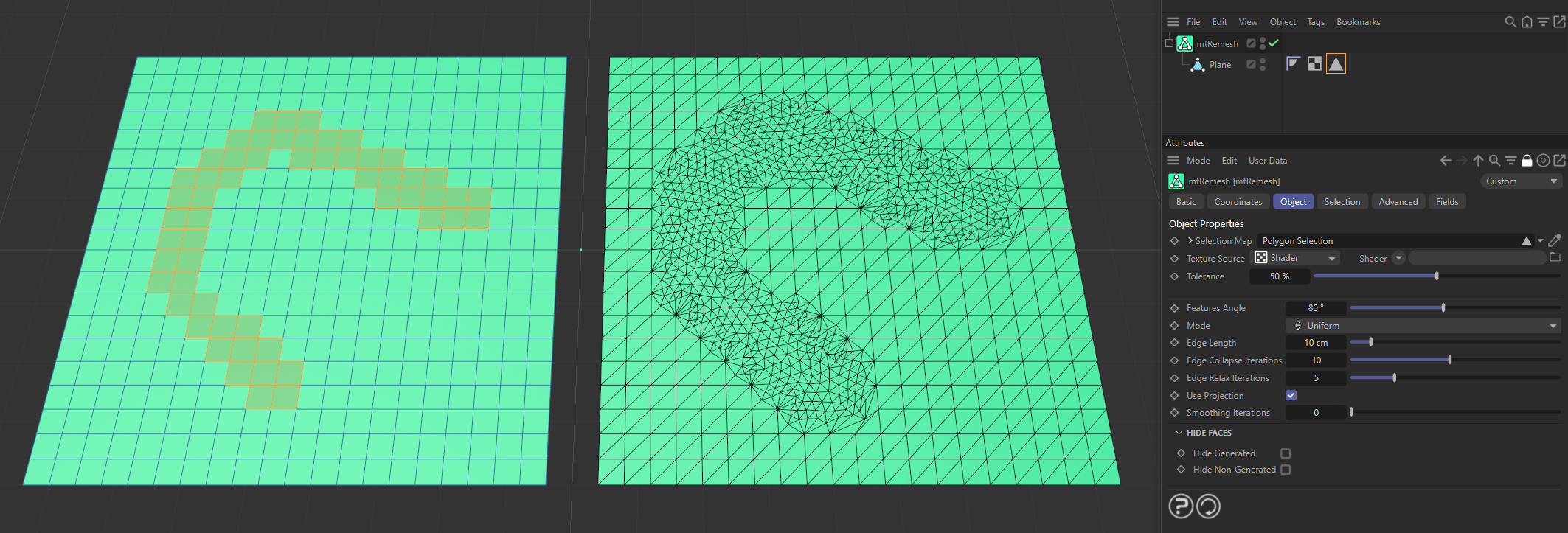
The Plane on the left has a vertex map, which is displayed in the viewport. An identical Plane is on the right, as a child of a mtRemesh. The vertex weights are driving where remeshing occurs.
Texture Source
You can use shaders, images and even animated video sequences to control where remeshing occurs. There are two options: Shader (the default option) and Texture Tag. Both use color value to define which areas are affected.
Texture Tag mode
This option requires a Cinema4D material. Place the material on the mtRemesh and you will see a texture tag appear alongside it in the Object Manager. Simply drag this texture tag into the Texture Tag link field.
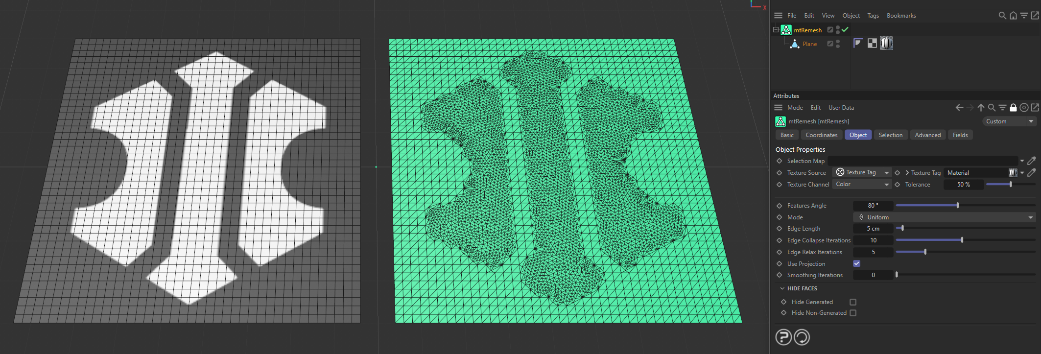
Texture Source set to Texture Tag, with the Noise material on the left driving the remeshing on the right-hand Plane.
Shader mode
Use the Shader drop-down to select an image, sequence or shader.
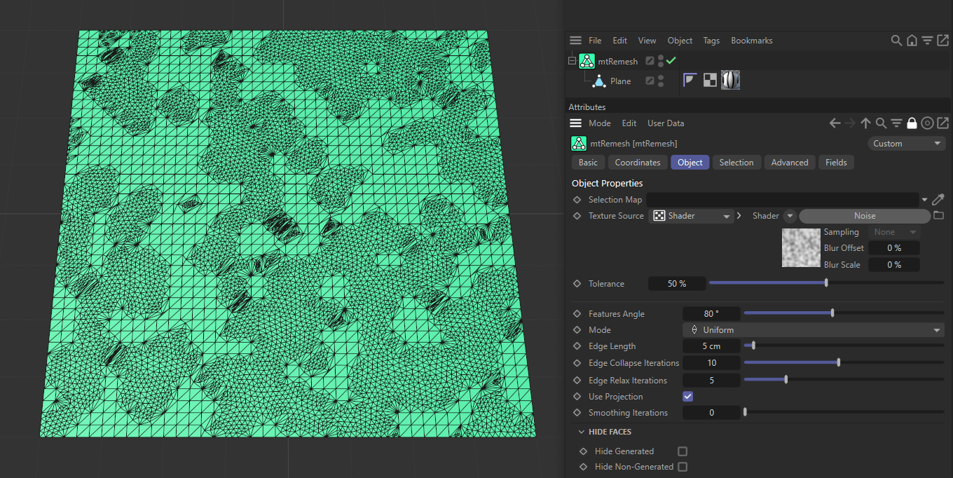
Remeshing in Shader mode with a Noise setting. Only the lighter areas are remeshing, not the dark areas.
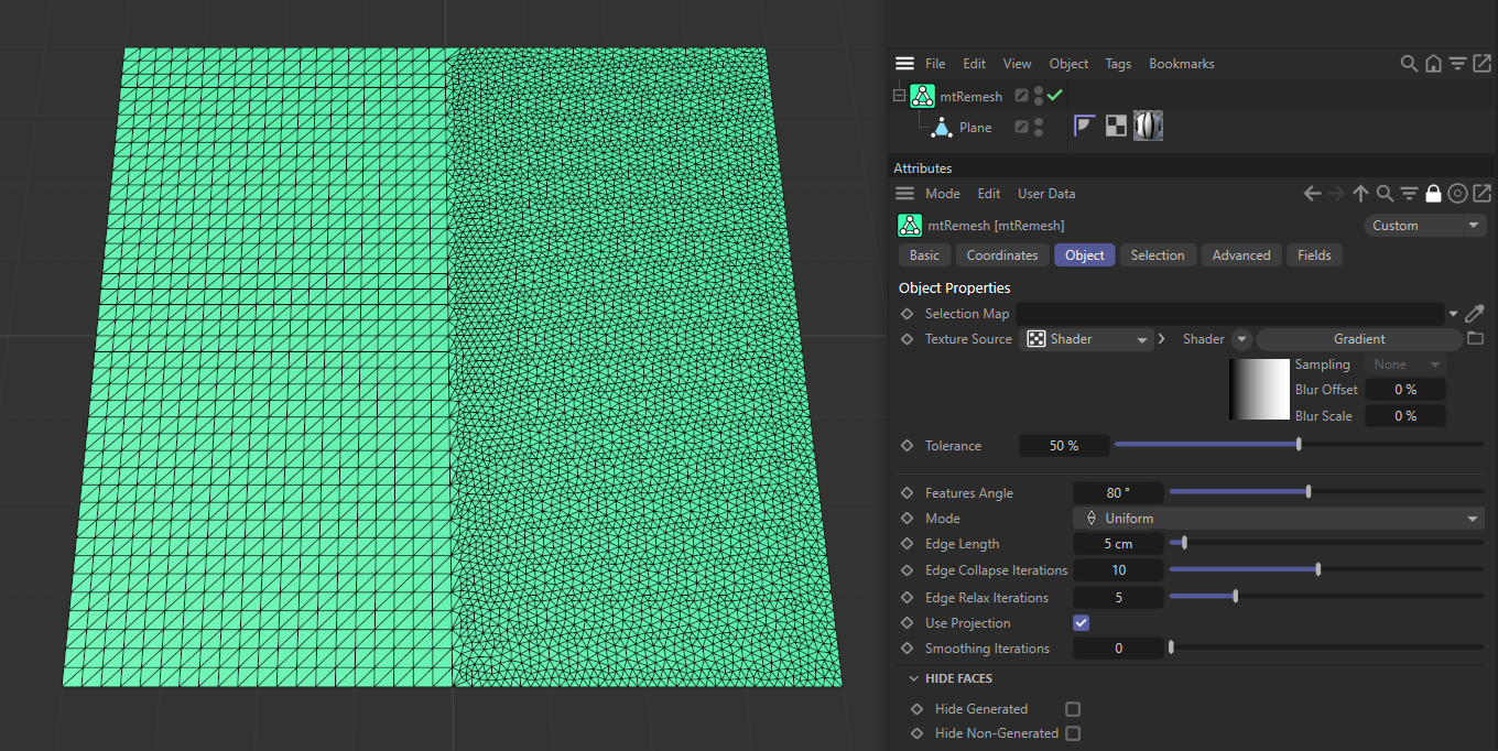
Remeshing in Shader mode with a Gradient setting; the brighter areas are remeshing.
Tolerance
The Tolerance slider will adjust the point at which remeshing occurs.
Lower tolerance values will allow remeshing in darker areas. Higher tolerance values will only allow remeshing in lighter areas.
Animation to demonstrate the effect of the Tolerance slider.
Features Angle
This slider controls where you are remeshing. Only edges that exceed the Features Angle setting will be remeshed. Use this setting to preserve original mesh edges.
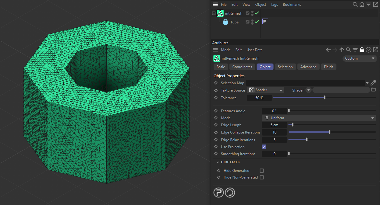
At 0 (zero) degrees, the original edges are retained and nothing is remeshed; every polygon is triangulating with an Edge Length set at 10cm.
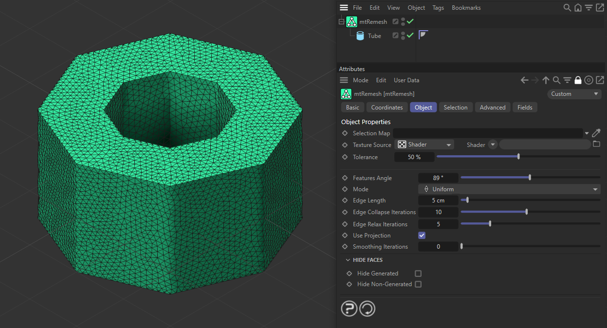
With the Features Angle set at 89 degrees, the cap edges retain their original hard edges, as they are 90 degree angles.
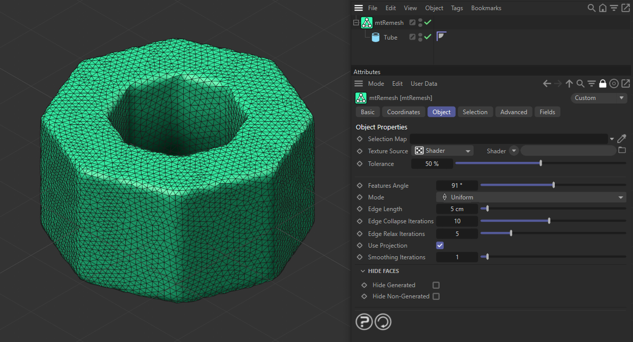
With the Features Angle set at 91 degrees, every angle that is more than 90 degrees is being remeshed and none of the original edges have been retained.
Mode
The settings are: Uniform or Adaptive.
Uniform setting
Polygon edge length will be as even as possible, giving triangles of equal size.
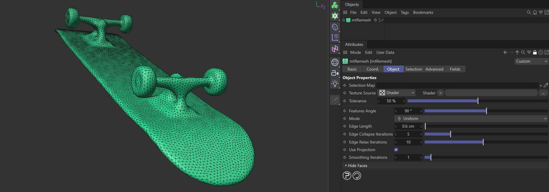
Mode setting as Uniform, generating polygons of equal size in remeshing.
Edge Length
This sets the length of each edge and, therefore, the size of each polygon.
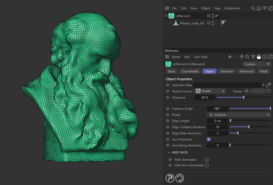
With a Features Angle set at 180 degrees (the mode is Uniform, with an Edge Length of 3cm), everything is being remeshed.
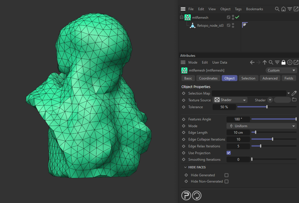
Here, the Edge Length has been changed to 10cm.
Adaptive setting
Polygons can differ in size, depending on the geometry. Broad areas of the base mesh will use larger polygons and detailed areas will use smaller ones. The limits of the polygon size range are set using the edge parameters below.
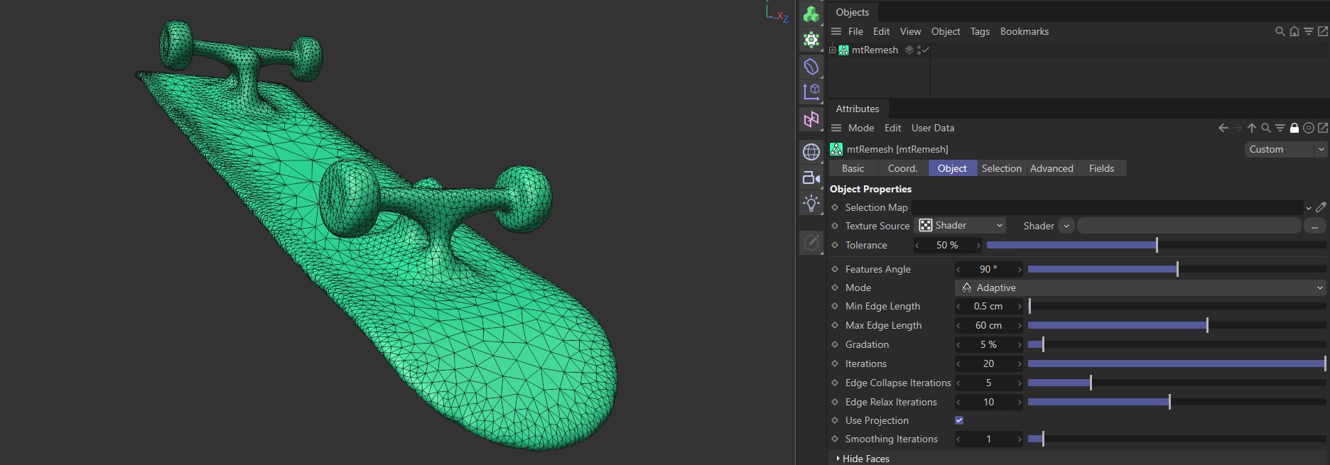
Mode setting as Adaptive, generating polygons of different sizes relative to the geometry that is being remeshed.
Min Edge Length
Sets the minimum edge length of the remeshed polygons.
Max Edge Length
Sets the maximum edge length of the remeshed polygons.
Gradation
This slider further controls the placing of the smaller and larger remeshed polygons. At a lower setting, there will be more of the smaller-length polygons, closer to the Min Edge Length setting.
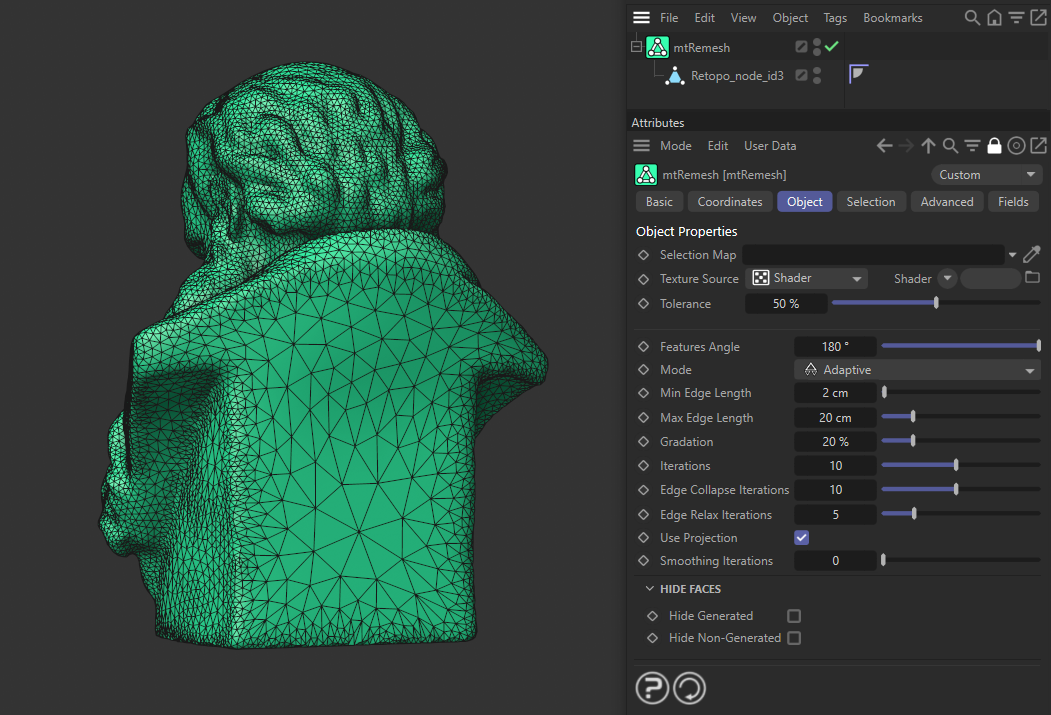
With a Gradation value of 20%, a combination of small and large polygons are generated.
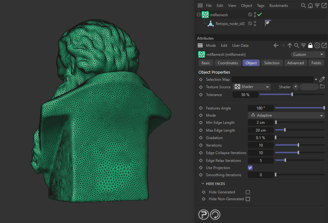
With the Gradation set at a lower value of 0.1%, many more of the smaller, remeshed polygons are generated.
Iterations
Each iteration is one running of the adaptive algorithm required to remesh. More iterations increase the quality of the mesh and more accuracy in the remeshing process, but this takes longer to calculate. In most cases, you can leave this at its default.
Edge Collapse Iterations
More iterations will help to collapse edges with polygons of differing lengths.
Edge Relax Iterations
In more complex meshes, it is possible for the remeshing process to produce intersecting edges; increasing the Edge Relax Iterations value can help to prevent this.
Use Projection
The UVW data of the base geometry is used in the remesh to help retain the object’s curvature. This setting also ensures that the UVW output of your original geometry is retained.
Smoothing Iterations
The higher the setting, the more the edges and corners in the mesh are smoothed.
Hide Faces
Hide Generated
The remeshed polygons are hidden from the viewport.
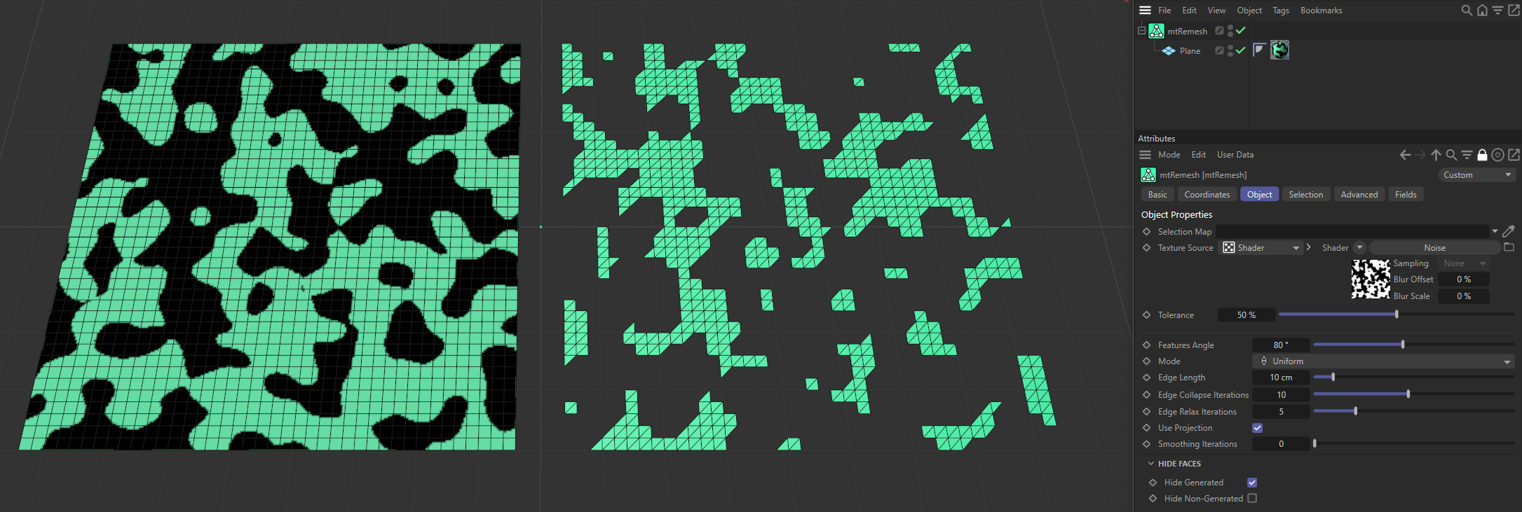
With Hide Generated enabled, all remeshed polygons are hidden.
Hide Non-Generated
The polygons which have not been remeshed are hidden from the viewport.
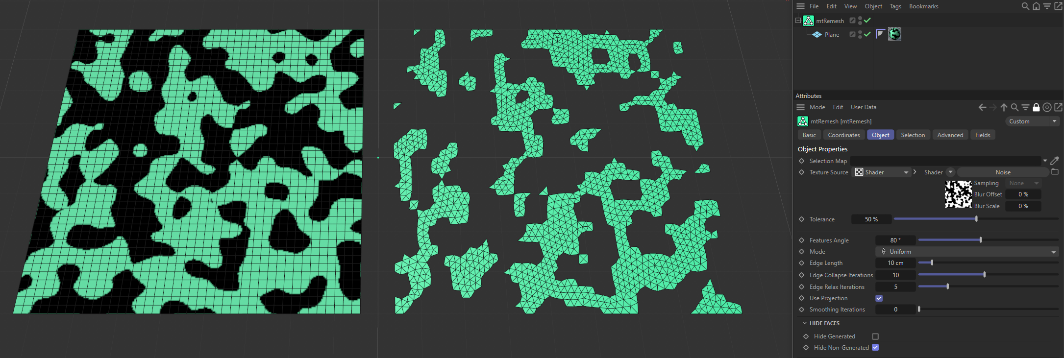
The same scene as above, but the Hide Non-Generated setting is enabled this time.
Selection
You can create polygon selections based on the mtRemesh operation. Each selection is stored within a selection tag, which is automatically generated on activation.
Each selection can be visualized by activating Display Selection. You can change the color of the displayed selection using the color picker.
Generated
Adds selections for the generated polygons.
Non-Generated
Adds selections for the non-generated polygons.
Display Selection
Displays the selection, using a color, set by the color picker.
Advanced
Optimize
Newly generated topology can include unused or duplicated points and surfaces. These can be eliminated by selecting Optimize.
Polygons
One or two-point surfaces will be eliminated.
Unused Points
Any unused points will be deleted.
Points
Duplicated points will be eliminated.
Tolerance
Duplicated points are merged if they are within the Tolerance range setting.
Fields
You can use the Fields options to control where you are remeshing your objects.
Animation demonstrating a Linear Field driving the remeshing.