 mtDualGraph
 mtEdgeSpline
 mtInset
 mtSelect
 mtShellGen
 mtShortestPath
 mtSplineSample
 mtSubDivider
 mtRemesh
 Global Settings
 Sphere
 Tree
Tree Koch
Koch Dragon
 Fern
Fern Fibonacci
 mtPolyScale
mtPolyScale controls the scale of an object’s individual polygons for procedural growth.
Overview Video
Cube as a child of mtPolyscale, with variation of scaling on each polygon.
Object
Object Properties
Selection Map
You can use vertex map or selection tags to define where scaling is performed. Drag the tag from the Object Manager into the Selection Map link field.
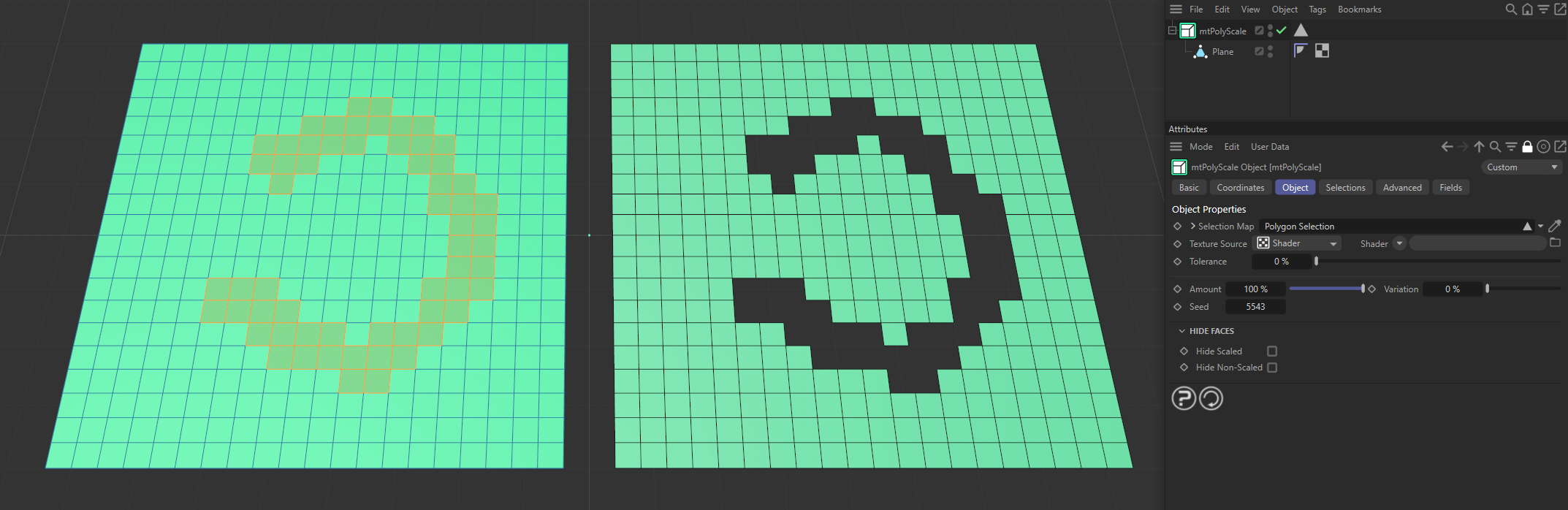
The Plane on the left has a polygon selection tag, which is displayed in the viewport. An identical Plane is on the right, as a child of a mtPolyScale, defining where scaling is being performed.
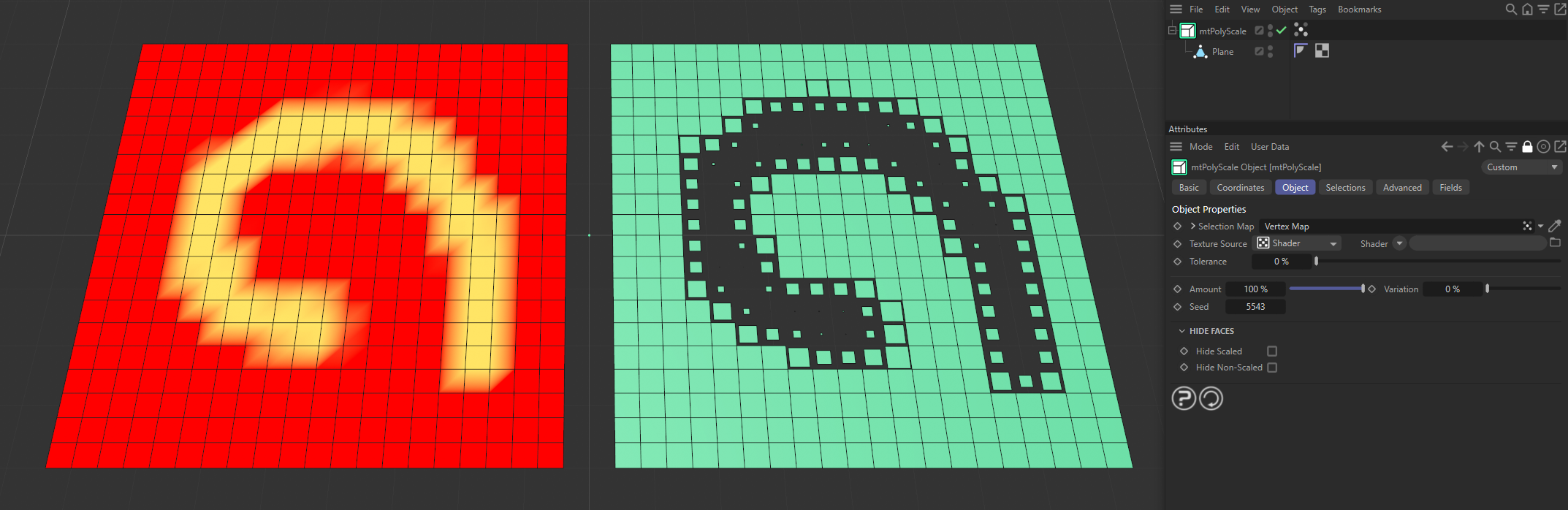
The Plane on the left has a vertex map, which is displayed in the viewport. An identical Plane is on the right, as a child of a mtPolyScale. The vertex weights are defining where scaling is happening.
Texture Source
You can use shaders, images and even animated video sequences to control where scaling is performed. There are two options: Shader and Texture Tag. Both use color values to define which areas are affected.
Texture Source set to Texture Tag, with the bitmap material driving the scaling on the Plane, which is, in turn, being controlled by the Amount slider.
Texture mode
This mode requires a Cinema 4D material. Place the material on the mtPolyScale and you will see a texture tag appear alongside it in the Object Manager. Simply drag this texture tag into the Texture Tag link field.
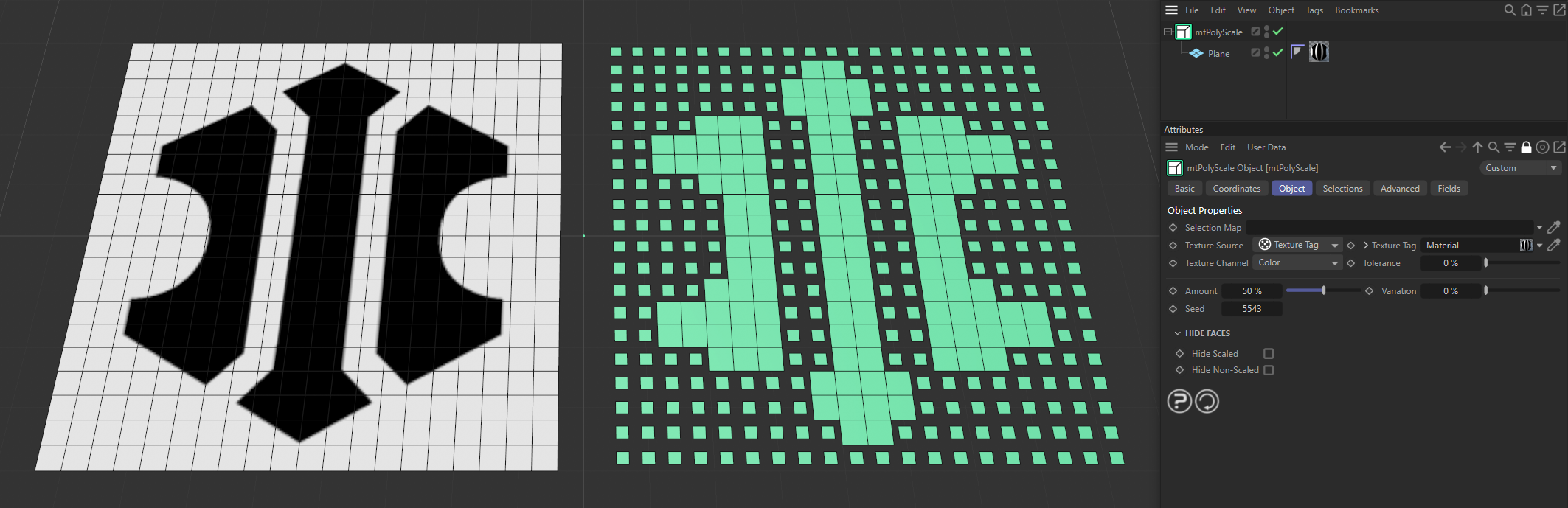
Texture Source set to Texture Tag, with the bitmap material on the left driving where the scaling is happening on the right-hand Plane.
Texture Channel
Use the Texture Channel pull-down to select which material channel you wish to reference. This is set to Color by default.
Other options are: Luminance, Transparency, Reflection, Environment, Fog, Bump, Alpha, Specular, Specular Color, Glow, Displacement, Diffusion and Normal.
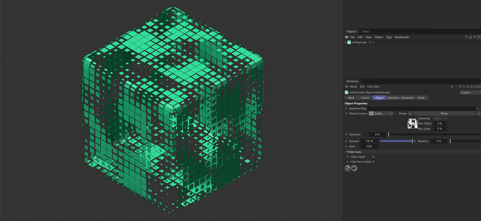
Shader mode
Use the Shader drop-down to select an image, sequence, or shader.
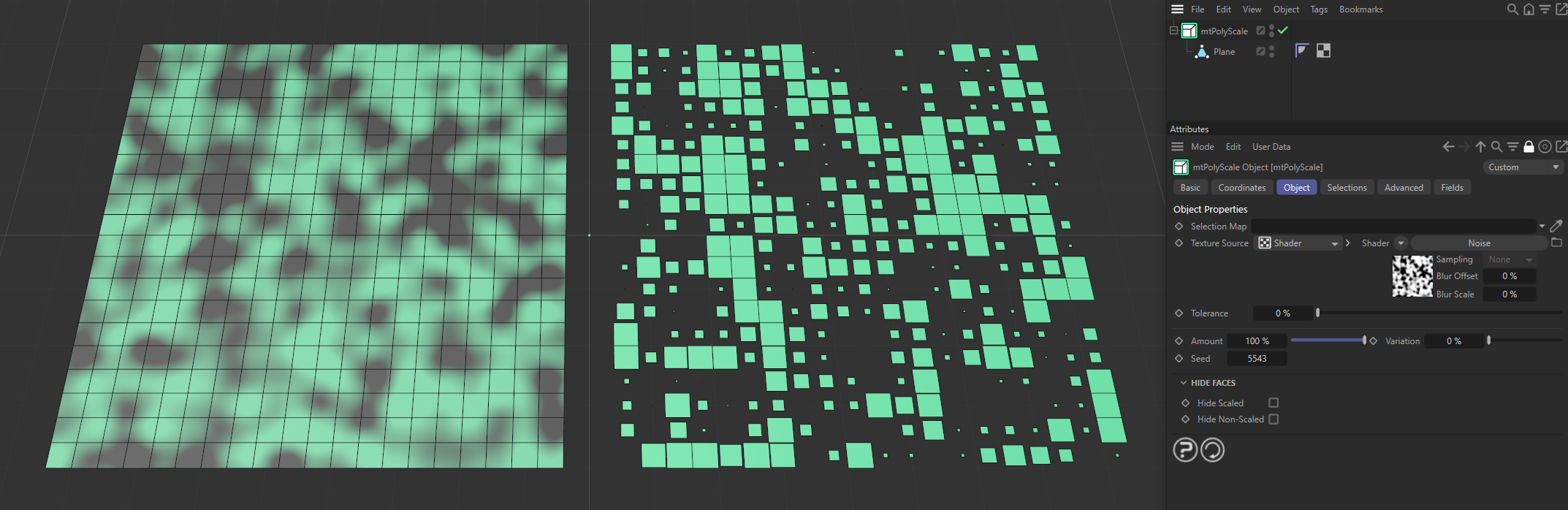
In this image, a Noise shader has been used and the brighter areas in the Noise pattern are being scaled down.
Tolerance
Use the Tolerance slider to control the contrast, adjusting the areas where scaling is performed, dependent on the values in the shader. Lower tolerance values will scale more polygons. Higher tolerance values will scale fewer polygons.
Amount
The higher the percentage value, the more the scale of each polygon is reduced.
Animation to demonstrate use of the Amount slider on the scaling.
Variation
An increase in this field varies the amount of scaling on each polygon.
Animation to demonstrate the effect of the Variation slider on the Amount setting.
Seed
Changing the Seed value alters this random variation, giving a different ‘look’ with each setting.
Hide Faces
Hide Scaled
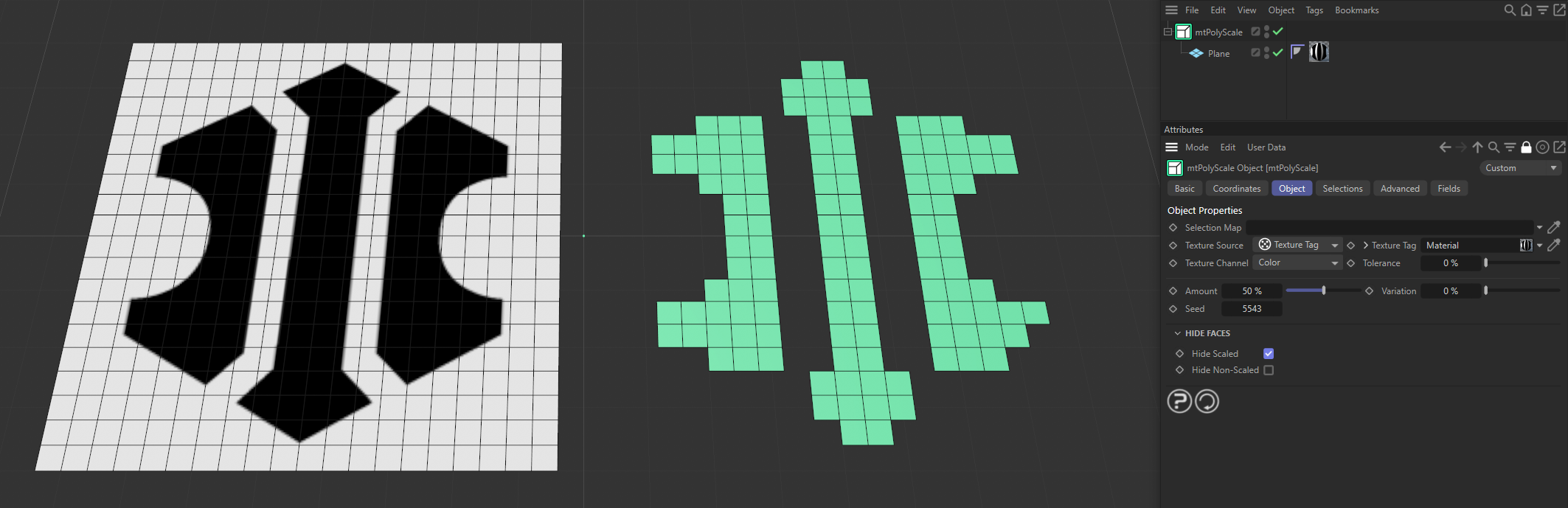
The polygons which have been scaled are hidden.
Hide Non-scaled
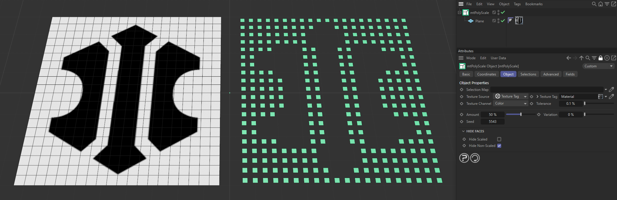
The polygons which have not been scaled are hidden.
Selections
You can create polygon selections based on the mtPolyScale operation. Each selection is stored within a selection tag, which is automatically generated on activation.
Each selection can be visualized by activating Display Selection. You can change the color of the displayed selection using the color picker.
Generated
Adds selections for the generated polygons.
Non-Generated
Adds selections for the non-generated polygons.
Display Selection
Displays the selection, using a color, set by the color picker.
Advanced
Optimize
Newly generated topology can include unused or duplicated points and surfaces. These can be eliminated by selecting Optimize.
Polygons
One or two-point surfaces will be eliminated.
Unused Points
Any unused points will be deleted.
Points
Duplicated points will be eliminated.
Tolerance
Duplicated points are merged if they are within the Tolerance range setting.
Fields
You can use the Fields options to control where you are scaling your objects.
Animation showing the effects of a Linear Field on the scaling of polygons on the Plane.